I bought this Sinclair calculator off eBay with the intention of repairing it. The power supply rails, LED display and driver chips were working fine. The keyboard had several keys that did not show any connectivity which could be fixed. But the main C-595 calculator chip was faulty and outputting random signals.
The C-595 is of course unobtainable these days, so could we replace it with a suitably programmed Arduino chip and bring it back to life?
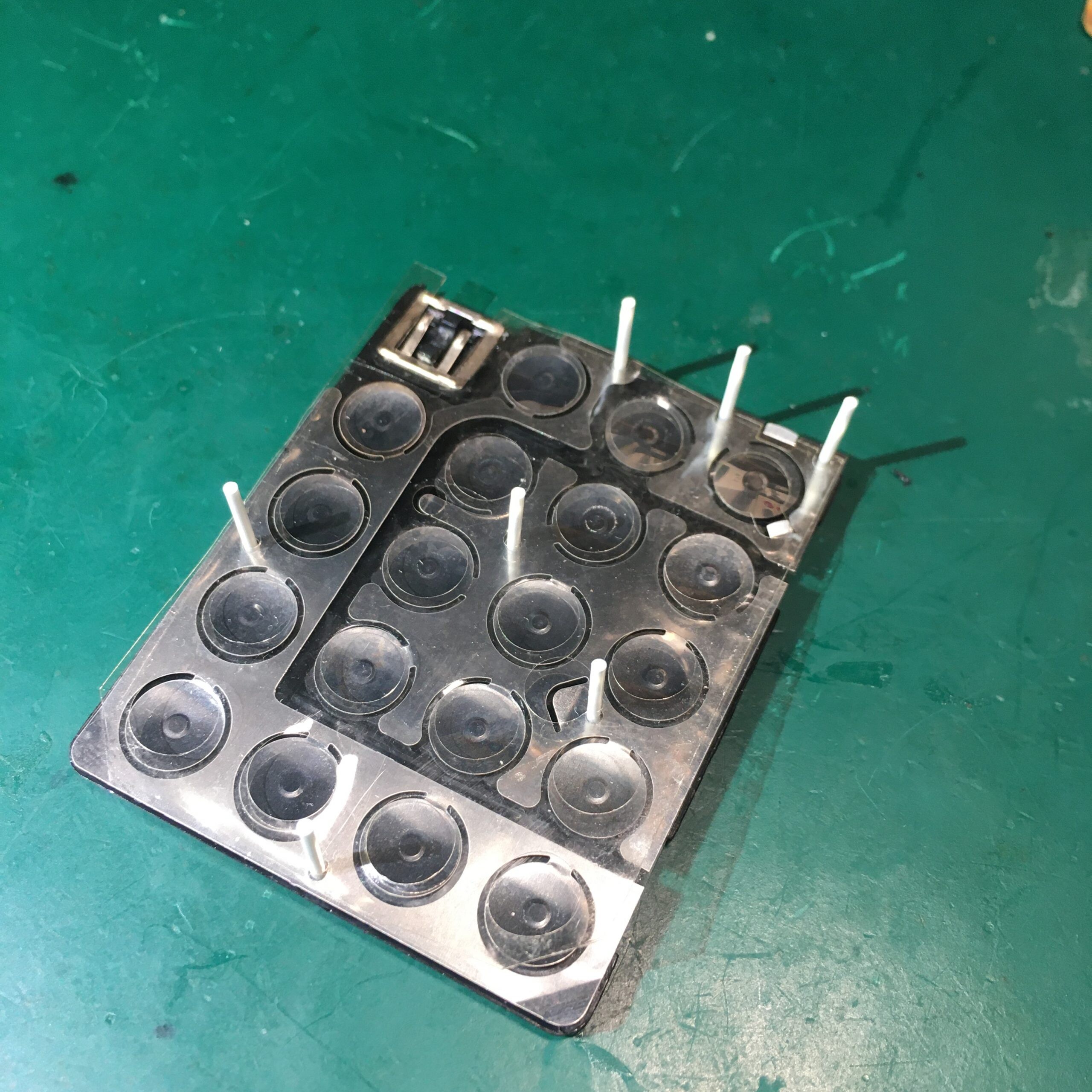
First job was to fix the keyboard. Several keys were not functioning so this needed a tear down and clean.
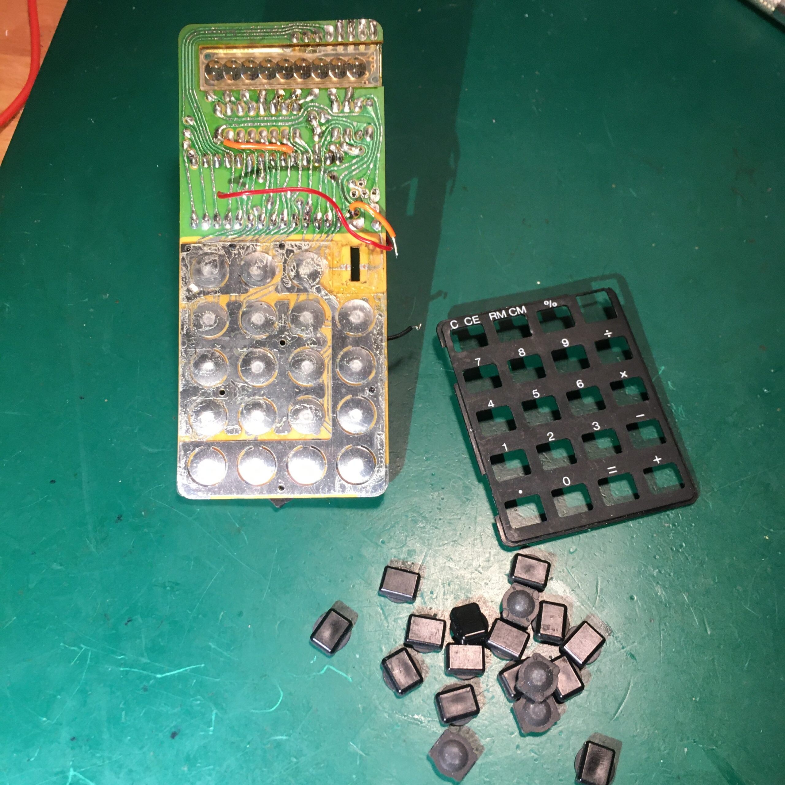
The keyboard was held in place by plastic pegs which naturally snap off when disassembling! Some small holes were drilled in the plastic frame using a hand held 1mm CNC drill bit taking care not to go through to the other side. Small lengths of 1mm ABS rod were then glued into the holes and melted with a soldering iron to keep the keyboard layers tightly sandwiched together.

With the keyboard working we turn attention to the main calculator chip. The plan was to design a small PCB carrier for an ATMega328 chip that could plug in in place of the original chip.
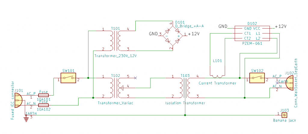
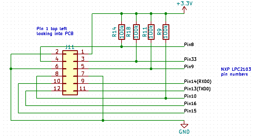
A datasheet is available for the C-595 (local copy here) and after some reverse engineering we arrived at the following schematic:
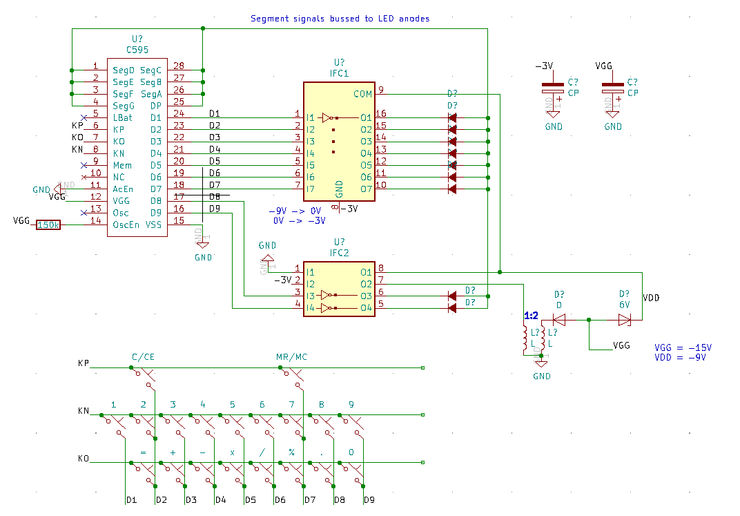
The C595 runs with a positive earth, so we’d have to install the Arduino upside down. A bit of a brain ache but it should work. I wanted to use the existing driver ICs to minimise changes.
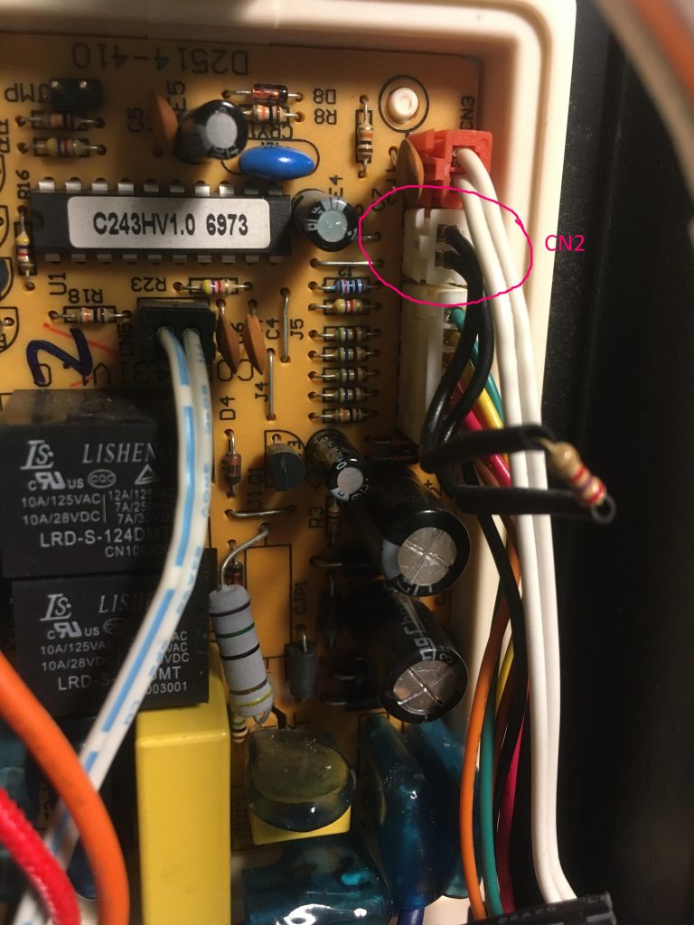
Removed the C595 IC and replaced with a socket. Removed the coil to disable 15V and 9V generation. Added a jumper wire to supply -3V battery power to an unused pin 10 on the socket.
The LED display is a 9 digit, seven segment common cathode device. To turn on a segment requires the segment line to be at 0V and the corresponding digit cathode at -3V. Allowing for the voltage inversion by the driver and the upside down Arduino, that corresponds to a HIGH for the segment and a HIGH for the digit.
To add to the fun the keyboard is multiplexed to the digit driver pins. An INPUT_PULLUP pin on the Arduino will pull to 0V, so we need to strobe the digit pins with -3V (LOW) to detect a change in state on the KP, KN and KO input pins.
We need 17 digital outputs and 3 digital inputs. To run at low voltage we use the internal oscillator which helpfully frees up pins PB6 and PB7 for use as GPIO.
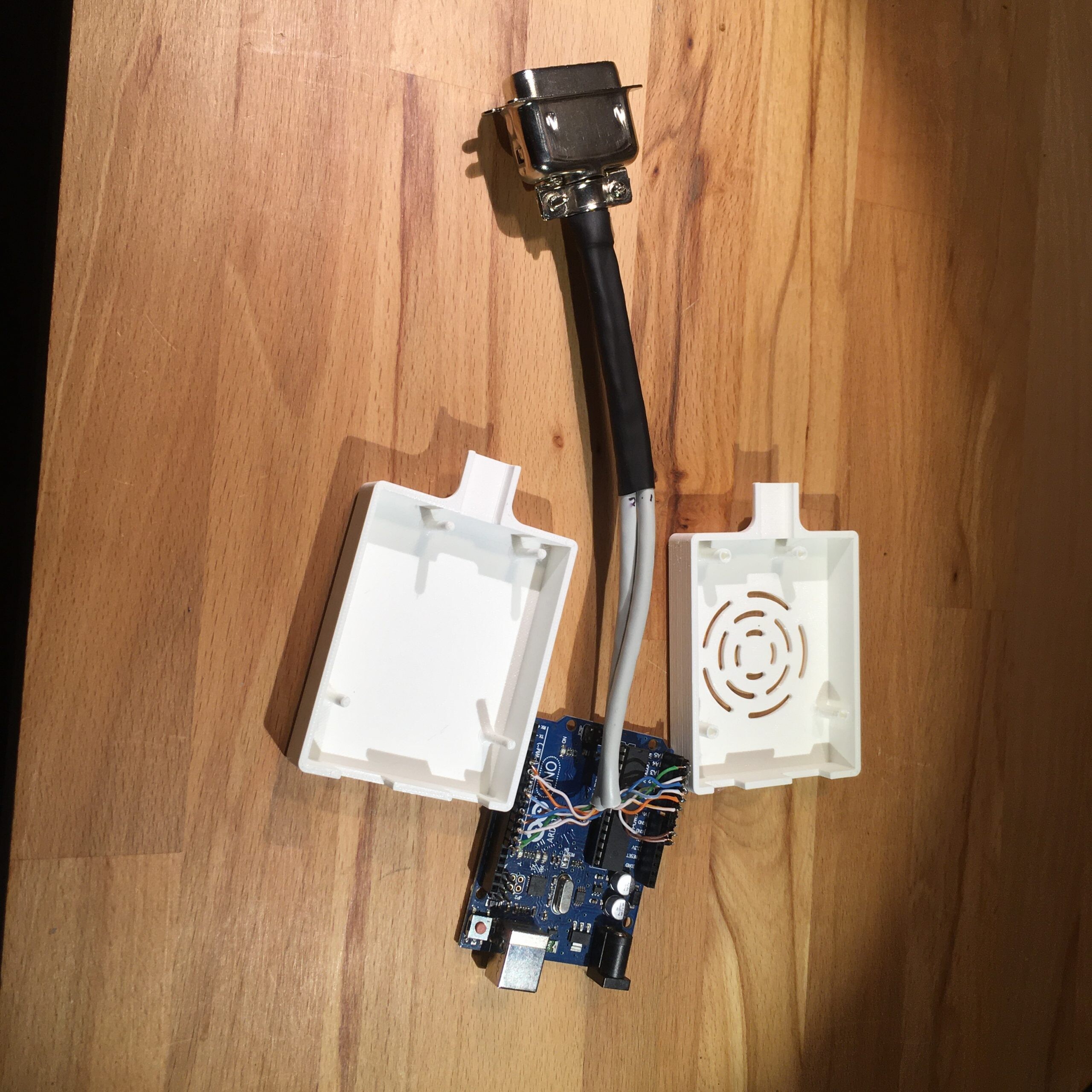
The software was developed initially as a prototype running on an Arduino Nano. It runs in a loop with three main functions; update the display, read the keyboard and update the calculation when a key is pressed. Updating the display is slightly complicated by the fact that the circuit uses the same pins to enable display digits as well as drive the keyboard. We need to take care to blank the display while the keyboard is polled. For the calculator part of the software a simple state machine is used in conjunction with a custom decimal floating-point library. Firmware can be found in this github repo
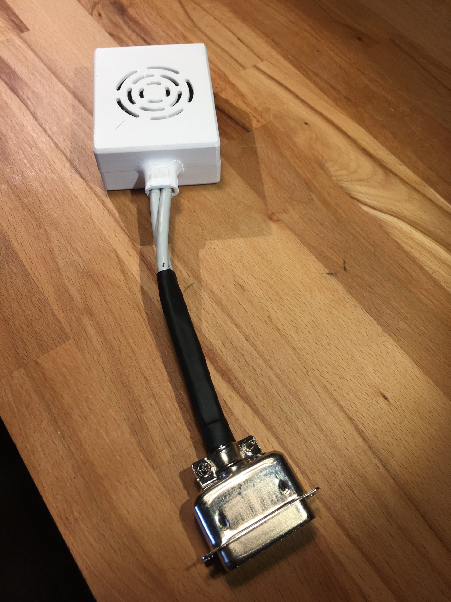
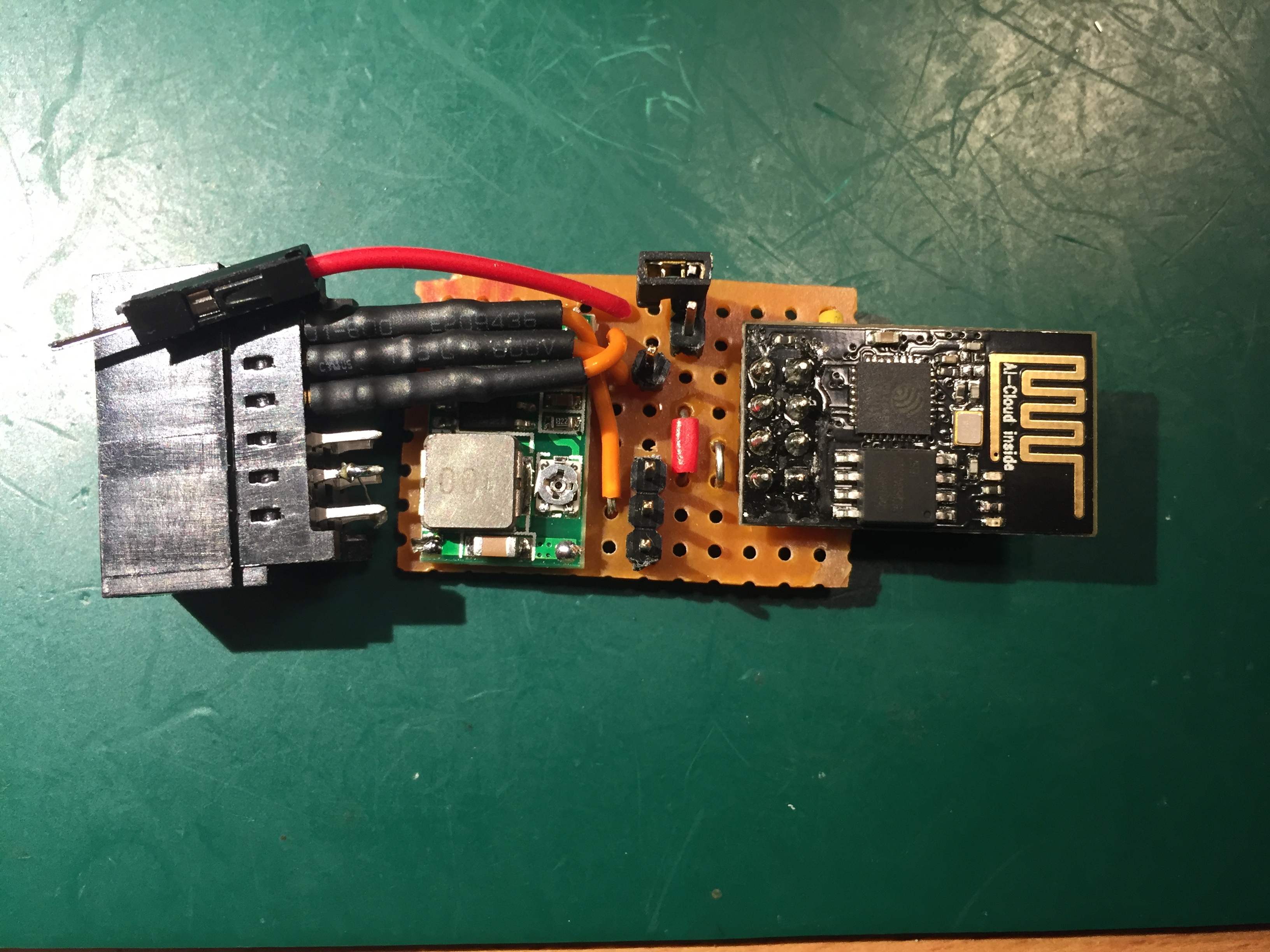
Here is a picture of the prototype:

The case wouldn’t close properly using the prototype so a small PCB was designed around a bare bones ATMega238P to fit in the C595 socket. The ICSP and Tx/Rx pins were connected to exposed pads for testing purposes.


An Arduino Uno was used as a programmer to flash the firmware to the ATMega using these pin connections.
PCB    ->  Arduino Uno
PIN 15 (VCC) -> 5V
PIN 10 (GND) -> GND
PIN 7 (KO, MOSI) -> 11 (MOSI)
PIN 8 (KN, MISO) -> 12 (MISO)
J103 pin 5 (~RST) -> 10
PIN 16 (D9, SCK) -> 13 (SCK)
To support the bare board, definitions were loaded from: https://mcudude.github.io/MiniCore/package_MCUdude_MiniCore_index.json
We use the factory defaults of 1MHz internal oscillator and BOD disabled so no need to change the fuses. Just set the drop down menu items correspondingly.
Here is a short video with a demo of the finished calculator and a quick look inside.