Adding a fan to improve air circulation in this filament drier is a common mod. Here is my variation.
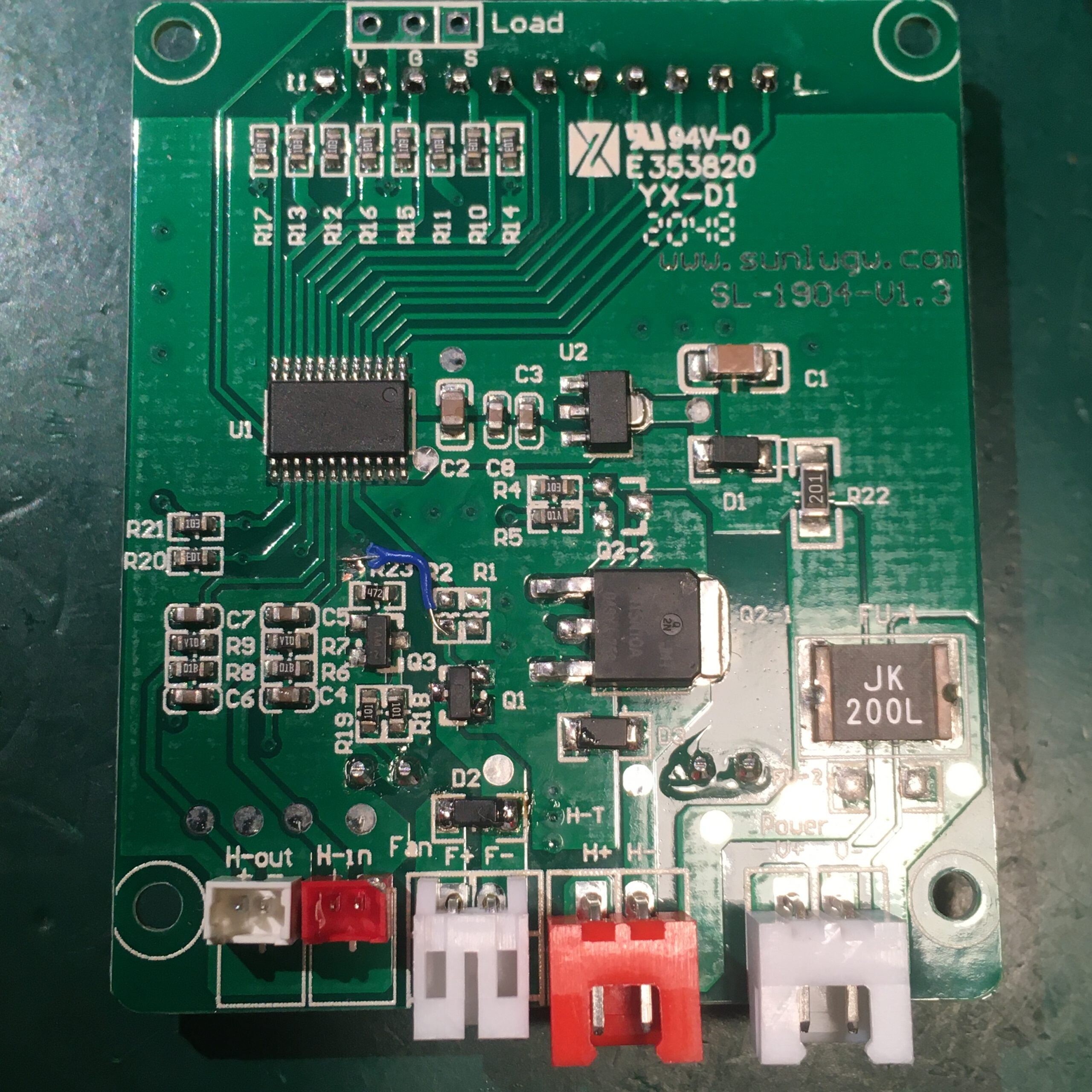
The first step is to source a voltage for the fan. The PCB already has unpopulated locations for fan components. I added a connector, diode D2 and a 30V n-channel Mosfet Q1. The gate of Q1 is connected to pin 16 of the MCU. This means the fan will come on when the LCD backlight is on.
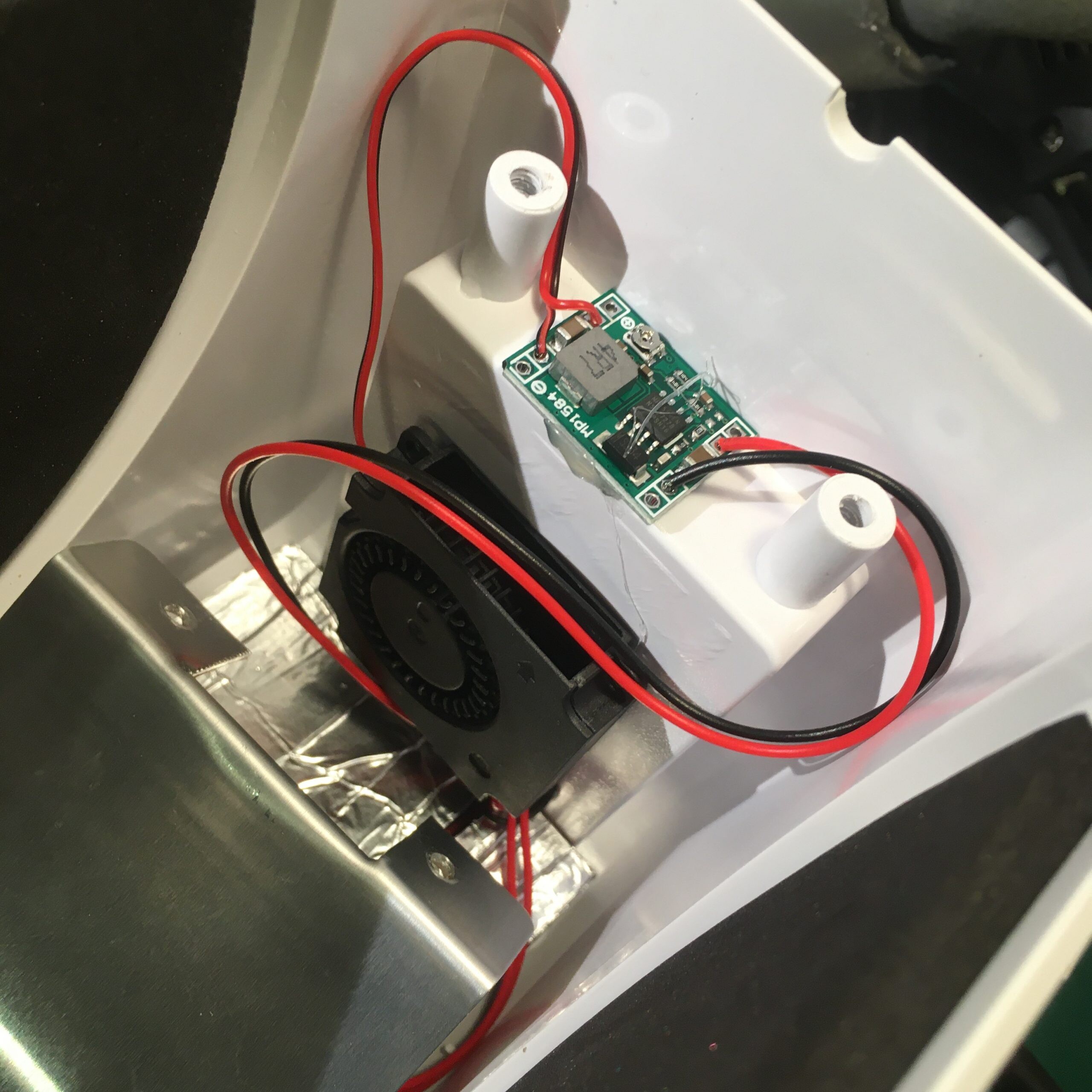
I fixed a 4010 24V fan behind the display with hot glue and cut a small opening in the hot plate to let the air circulate. I also wired up an MP1584 buck converter module to allow control of the fan voltage, speed and noise.
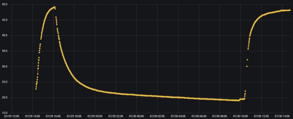
And here are the temperature profiles inside the unit measured at the top of a roll of filament. The first run is with the fan set to 12V. The second with no fan.
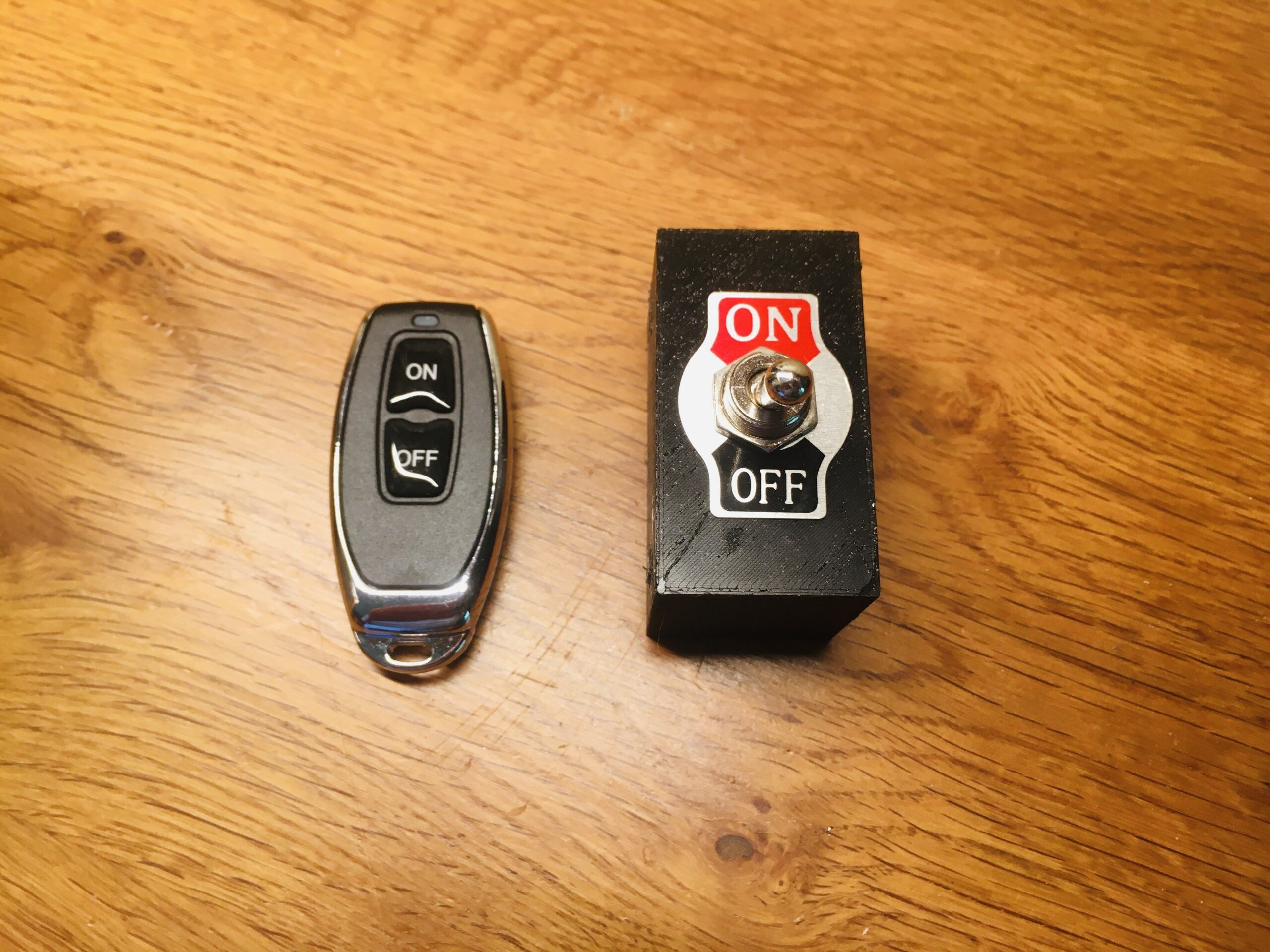
I have a wireless switch with a key fob style remote control. It works fine but the use of a toggle switch has been mandated 😉
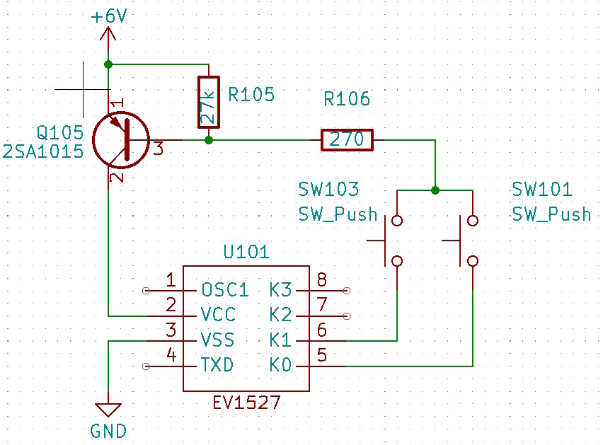
First task is to reverse engineer the remote control. It uses the common EV1527 encoder chip and relies on the data pins’ internal pulldowns to sink current when a button is pressed. This turns on the PNP transistor and powers on the chip.
The device operates off two coin cell batteries and I wanted to keep the device low power. The modified circuit for toggled operation is below:
As shown C101 will charge to +6V. When toggled, Q101 will turn on followed by Q102. C101 will discharge via R102 so after a delay Q101 and Q102 will turn off. Q102 is connected across the push button contacts so this will mimic a short button press. At the same time C102 is being charged ready for the next toggle.
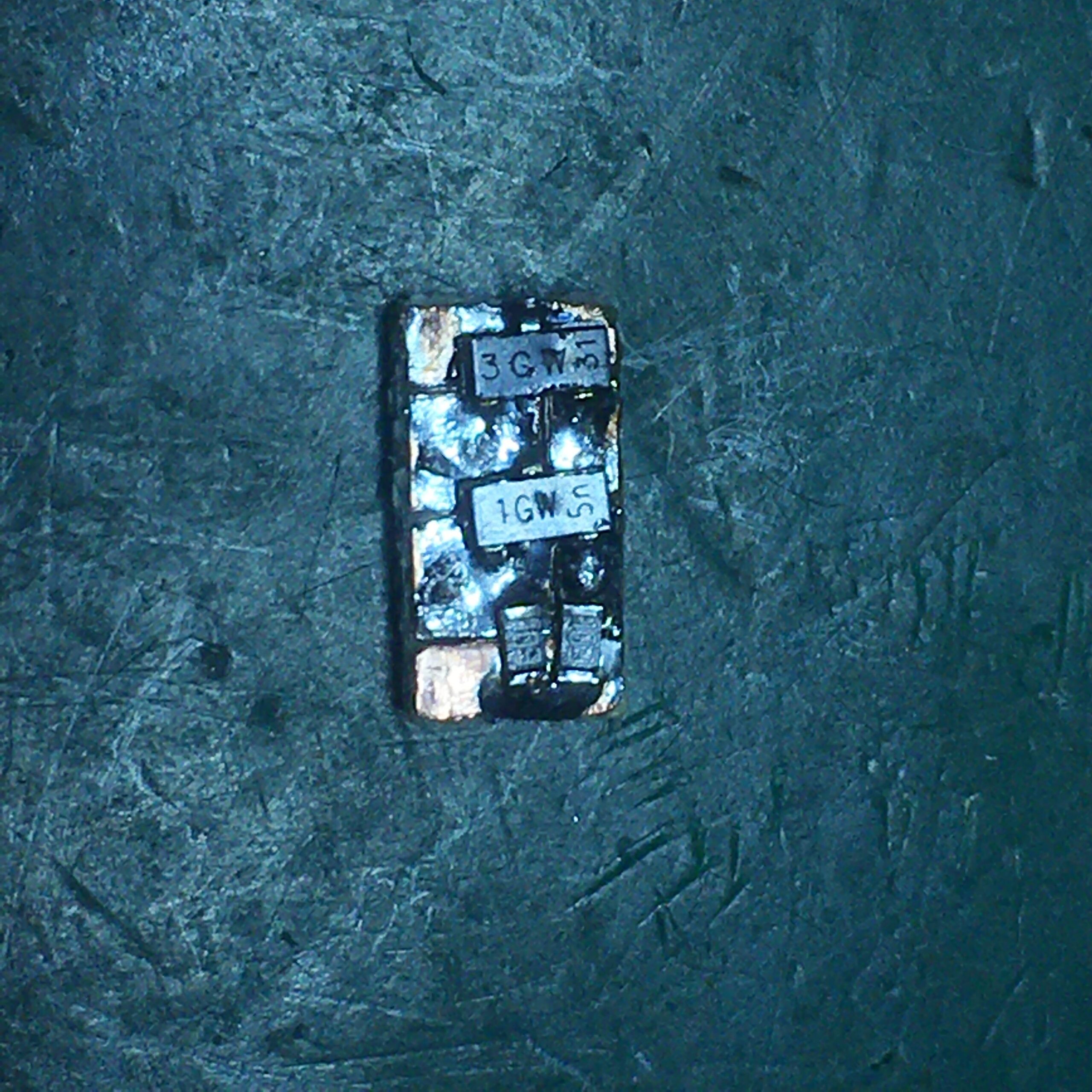
I made up the circuit on some copper clad board and wired it up to the toggle switch
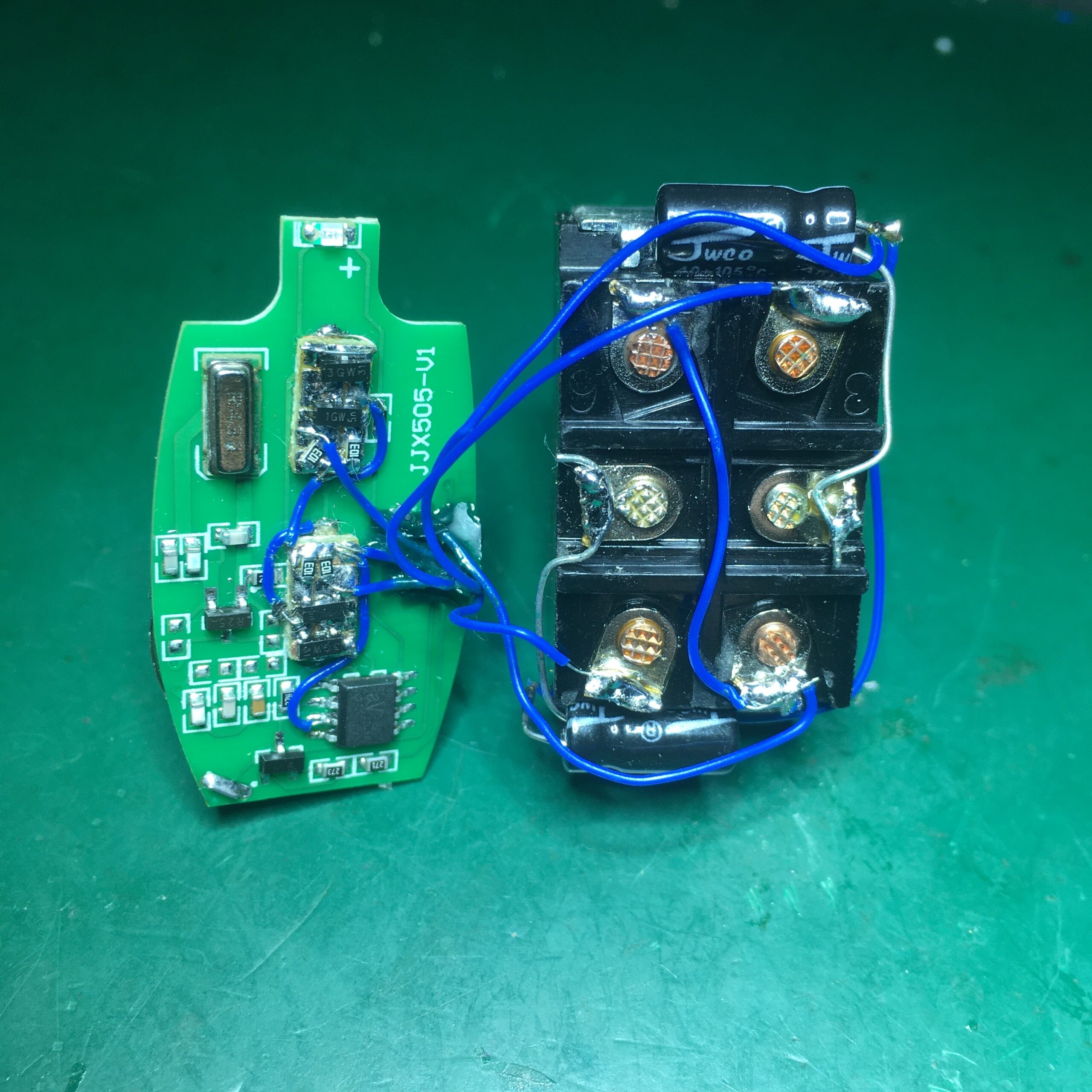
Followed by some Kapton tape and hot glue sandwich to give a compact result:
This was originally designed to just mirror a Rigol DS1054 screen over a LAN, but I couldn’t stop myself adding a few features, so you can now:
Click on the Timebase box to change the timebase
Click on the channel numbers at the bottom to toggle the corresponding channel on/off
Click on the channel voltage displays to change the vertical scales
Click and drag a trace to move it up/down (in Turbo mode only)
Click and drag in the “waveform memory” window at the top centre to move the traces left and right
Right-click on the main display to copy an image of the display to the clipboard or to a file
Right-click on the main display to turn Turbo mode on or off. With Turbo mode on only waveform data is downloaded and drawn over a screenshot. This can give a faster update rate but will obscure measurement data etc. With Turbo mode off the app simply mirrors the display at 1 FPS.
Here’s a screen capture showing it in use.
With just 1 channel enabled you get about 6 FPS (in Turbo mode) which drops to about 1 FPS with multiple channels. With Turbo mode off the whole screen is refreshed at 1FPS.
On first run it will ask you for the scope’s IP address. Enter it and click Save
The app is packaged as a UWP app and doesn’t require any VISA drivers to be installed.
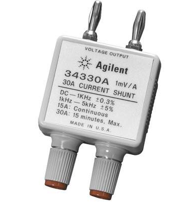
I needed a precision current shunt to calibrate a recently fixed E3631A power supply. The Agilent 34330A looks nice and is colour coordinated, but at $108 seemed a bit pricey for a resistor in a box.
Agilent 34330A
So let’s make a DIY clone…
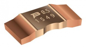
For the resistor we use an SMD Current Sense Resistor, 0.001 ohm, CSS2H-2512 Series, 2512 [6432 Metric], 5 W, ± 1%. This will give the required 1 mV/A response and can cope with a 30 A current.
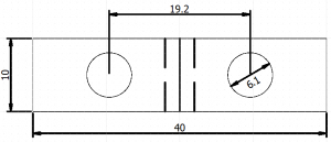
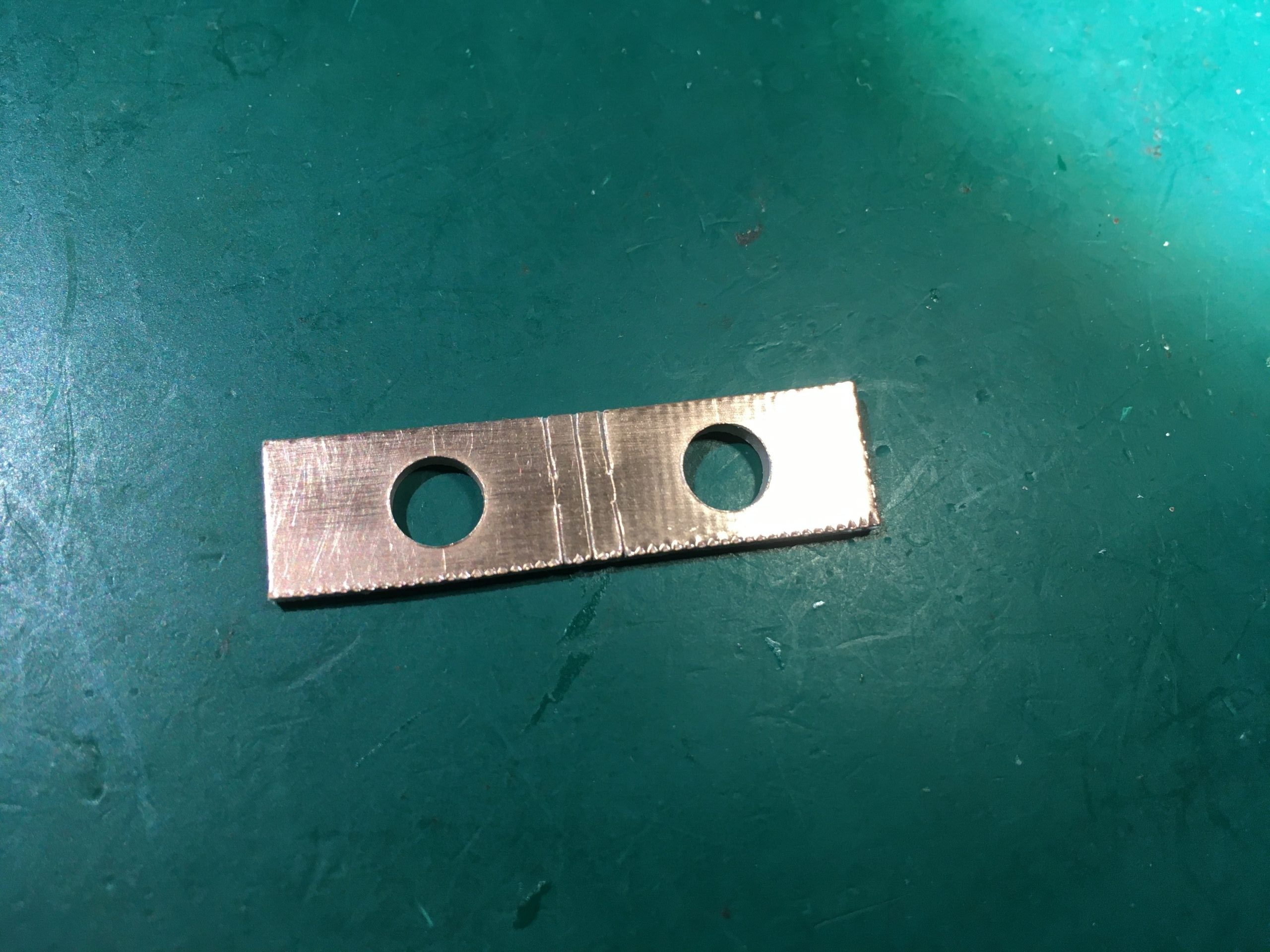
A small PCB was cut from a piece of copper clad FR4. The holes are 19.2 mm apart as this is a commonly used binding post separation. Care should be taken to route the sense connections as close to the ends of the resistor as possible.
The resistor and sense leads were soldered on
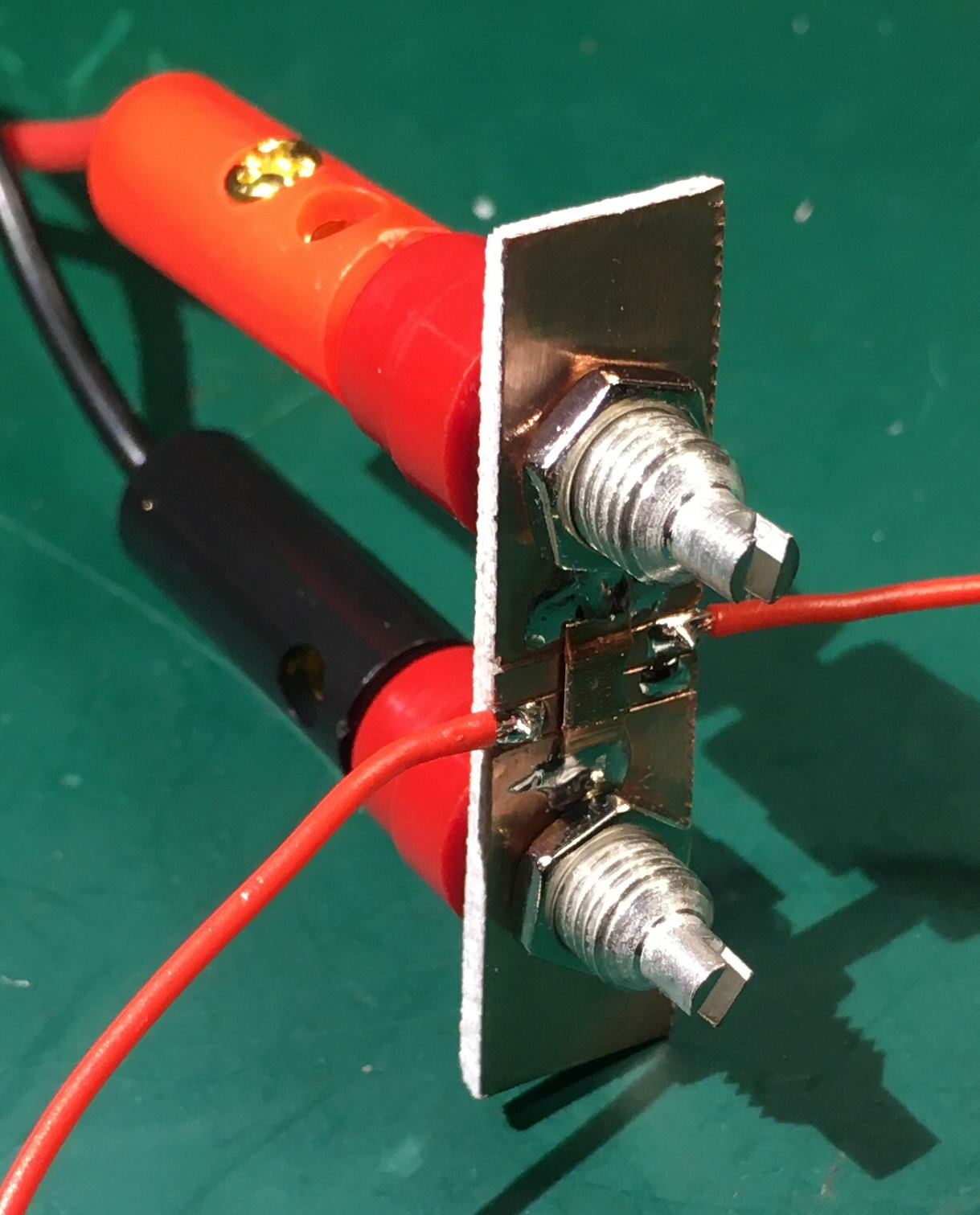
Mounted in a 3D printed box with banana sockets and plugs
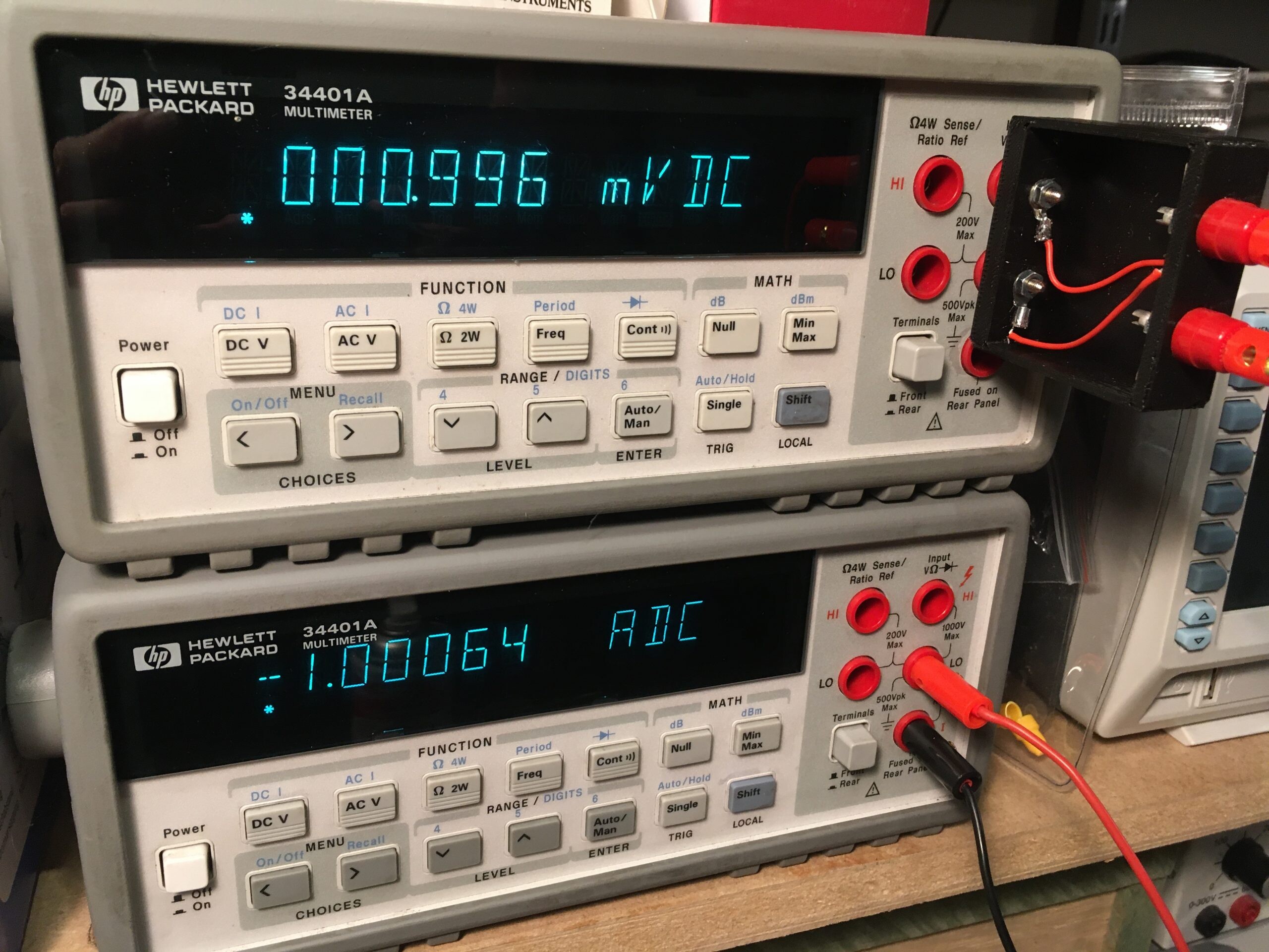
Here is the shunt under test showing we are within 1% tolerance.
A couple of lessons learned:
If any solder gets on the resistive part of the resistor it will reduce the resistance!
The sense connections must be connected as close to the ends of the resistor as possible. A few extra micro-ohms will exceed the tolerance.
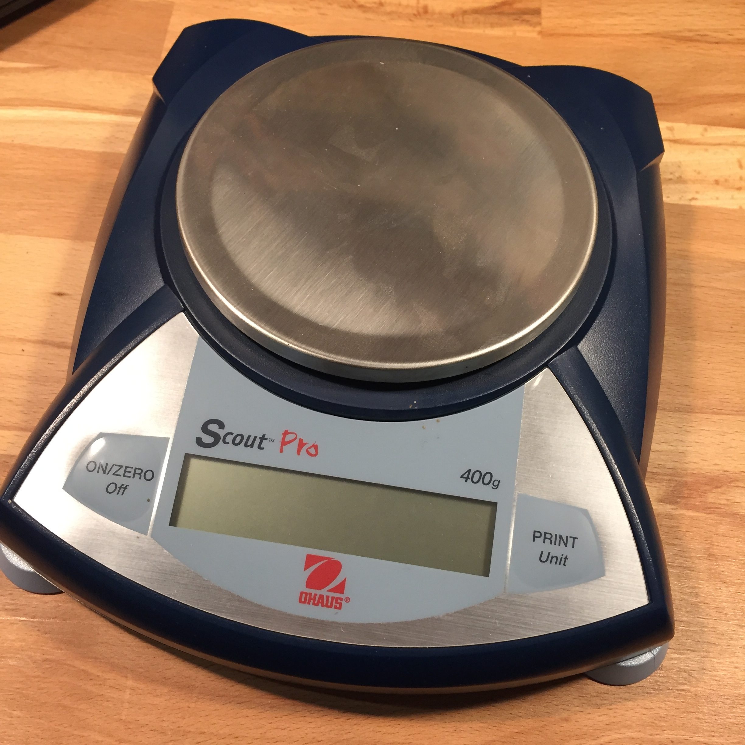
A potential project required wireless connectivity to an Ohaus Scout Pro SPU401 balance.
This balance takes a proprietary USB or RS232 adaptor which plugs into a 2×6-way edge connector on the PCB, but as an adaptor costs more than the balance cost on eBay it was decided to hack it.
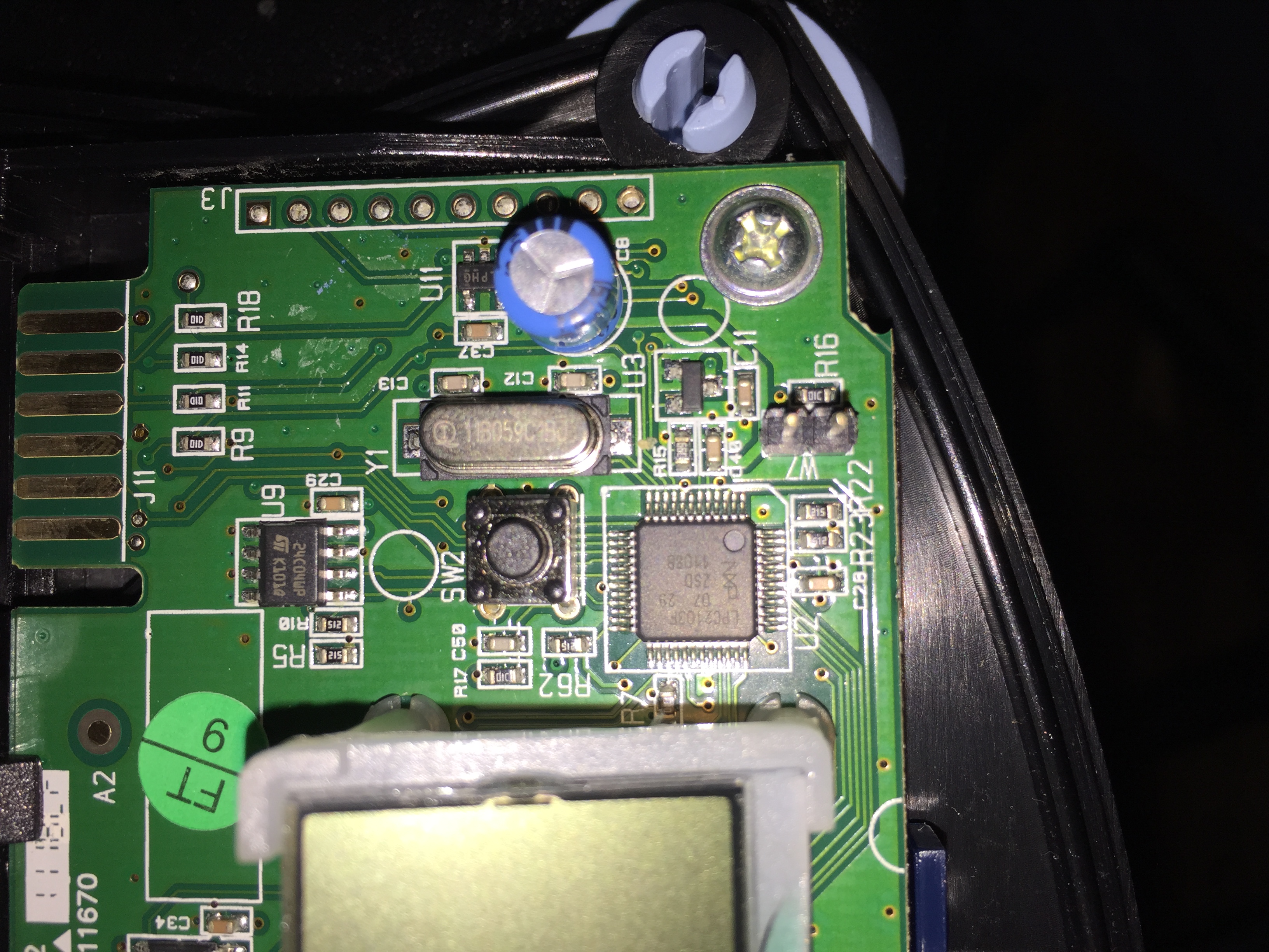
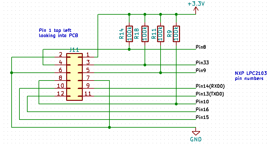
Tracing out the edge connector pins on the balance PCB to the NXP LPC2103 micro-controller revealed the following circuit fragment:
An extra menu item only appears on the balance’s display when a serial adaptor is plugged in, so a reasonable guess was that the lines with pull-up resistors are pulled low in some combination by the adaptor to enable the unit to recognise it. And indeed after some experimentation it was found that starting the unit up with pin 8 grounded adds the Print and USB options to the menu. Grounding pin 33 on startup adds Print and RS232 items.
Navigating through the new menu options, setting baud rate to 9600,N,1 and print setting to continuous non-stable showed the expected serial output on TXD0 pin.
Hardware
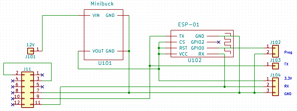
The idea was to use an ESP8266 module to send and receive serial data from the balance to an MQTT topic. The edge connector has a 3.3V pin available, however the balance powers off if more than about 100 mA current is drawn. This was not enough to power the ESP8266 so a mini-buck regulator was used and fed directly from the 12V input jack.
Final hardware schematic:
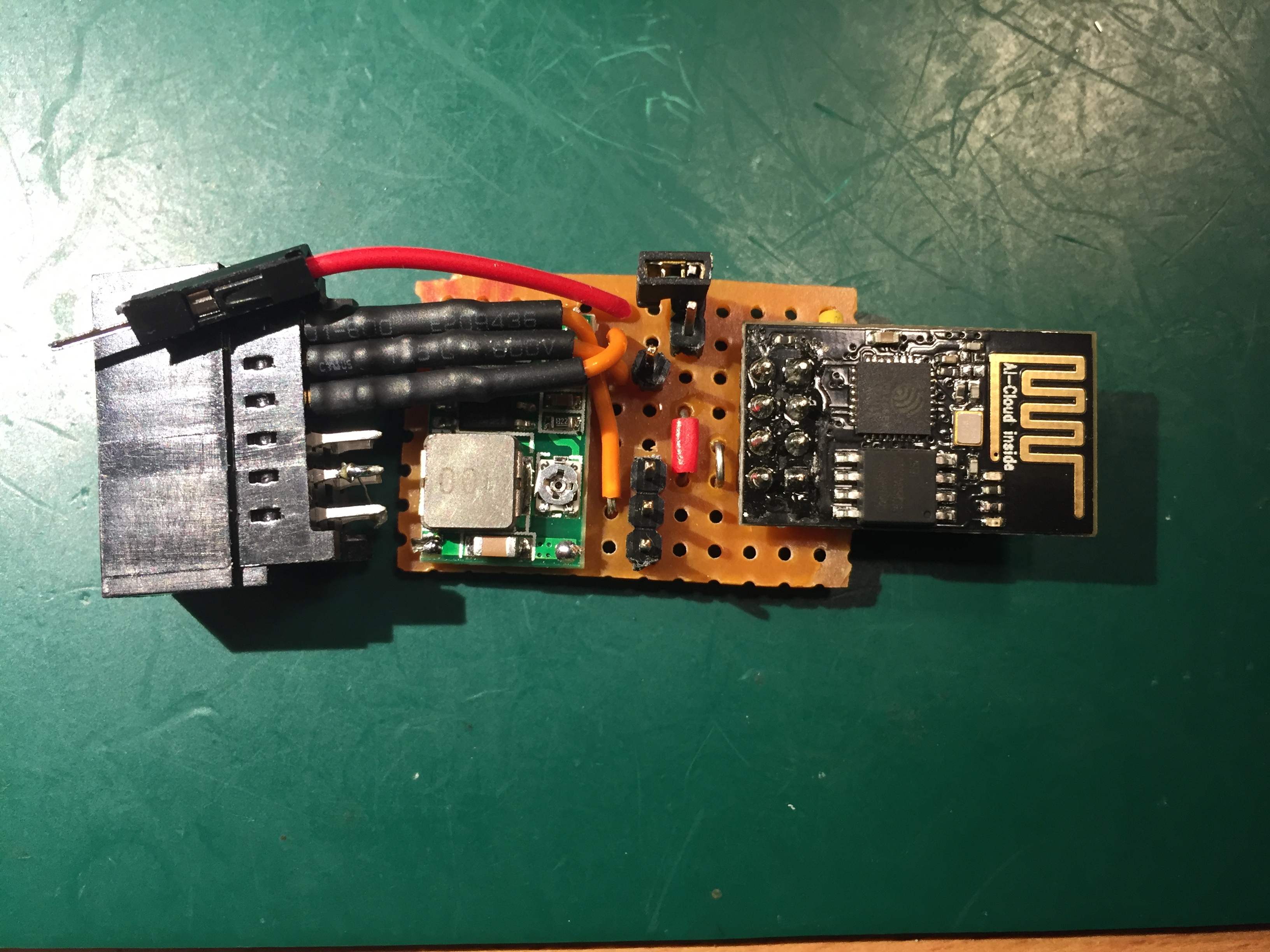
And all wired together on a small strip-board. A 12 way, 2 row, 2.54mm pitch female edge connector (RS718-8245) from TE was used:
Software
A simple program to send/receive any serial traffic to an MQTT topic was downloaded to the ESP8266. Commands can be sent to/from the balance by publishing/subscribing to the “ohaus” topic.
Part 1 described the hardware portion of this project. TL;DR: the existing microprocessor was replaced with an Arduino.
Part 2 covers the low level robot control and iRobot Create emulation software.
A couple of hardware modifications have been made since part 1 was written:
The Arduino Uno was replaced by a Nano. This is not only a lot smaller but also has a couple of extra IO ports.
A battery voltage sensor was added in the form of a simple 4:1 resistor divider.
Thearduino pin mapping is now:
μC Pin
Function
Arduino Pin/Dir
Notes
1
Right Bumper
D6 In
HIGH on bump
2
Over current
In
Unused
3
4
Right wheel forward
D10 Out PWM
IN1
5
Right wheel backward
D9 Out PWM
IN2
6
7
Fan & Side brush motor
Out
Unused
8
Wheels up
D11 In
All 3 wheels OR’ed
9
L switch
D12 In
LOW when pressed
10
L switch LED
D13 Out
Active LOW
11
12
M switch
A6 In
LOW when pressed
13
S switch
A7 In
LOW when pressed
14
Green LED
A2 Out
Active LOW
15
Red LED
A3 Out
Active LOW
16
M switch LED
A4 Out
Active LOW
17
S switch LED
A5 Out
Active LOW
NC
Battery Voltage
A0 In
Via 4:1 divider
19
20
GND
GND
21
Left wheel forward
D3 Out PWM
IN4
22
Left wheel backwards
D5 Out PWM
IN3
23
Left bumper
D2 In
HIGH on bump
24
Speaker
D4 Out
25
26
Main brush motor
A1 Out
Unused
27
28
29
30
31
32
33
34
35
Left wheel encoder
D7 In
36
37
38
39
Right wheel encoder
D8 In
40
+5V regulated
5V
For the software it was decided to emulate an iRobot Create 2. This has a documented API (iRobot Create 2 Open Interface) so all design decisions have already been made. Also, because this is a popular platform, third party software exists to directly control the robot and a driver for ROS integration is available.
Not all of the Open Interface commands were implemented, just those required for motor control, odometry and common sensors. The source code can be extended as needed. Some constants may need changing.
The code is straight forward in operation:
The serial port is monitored for any incoming commands. The commands are parsed and executed which results in motors running, sensor data being returned or robot state being updated.
Wheel encoder pulses are accumulated via two interrupt handlers
Every 15ms the internal state is updated. Sensor data is streamed out if requested. If the robot is moving, the motor power is updated. In normal driving mode (velocity and radius specified) a PID controller for average velocity is cascaded with another PID controller to keep the wheel speeds in the required ratio for the specified turn radius. In “Direct” driving mode (velocity of each wheel specified), two PID controllers, one for each wheel, are used to keep the velocities at the requested values
The Arduino PID Library is used with some modifications including bias value support
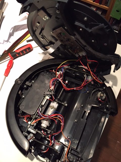
I needed a robot platform for a project and bought a Vileda A3 cleaning robot cheaply from ebay, advertised as not working but a new battery fixed that! (Battery for Vileda M-488a fits this A3 model)
Opening it up:
we find the expected motors for the wheels, fan, main brush and edge brush. The wheels are equipped with optical encoders. Other sensors include the left and right bumpers, wheel drop switches and cliff detectors. The top lid holds three buttons and a red and green LED. There is a 360 IR reflector installed but this is not populated with a detector.
There is a self-contained NiMH battery charger board under the top lid:
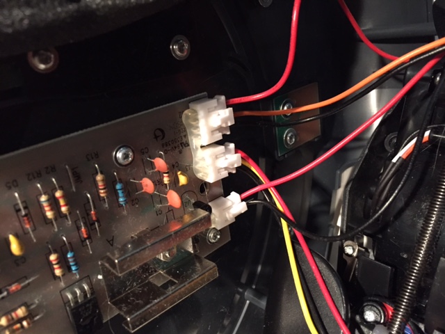
Rather than totally replace the existing PCB I decided to just replace the microcontroller (an 8051 clone) so I could keep the existing motor drivers, connectors etc
After a bit of reverse engineering I came up with the following PCB pin assignments:
μC Pin
Function
Arduino Pin/Dir
Notes
1
Right Bumper
D6 In
HIGH on bump
2
Over current
In
Unused
3
4
Right wheel forward
D10 Out PWM
IN1
5
Right wheel backward
D9 Out PWM
IN2
6
7
Fan & Side brush motor
Out
Unused
8
Wheels up
D13 In
All 3 wheels OR’ed
9
L switch
D12 In
LOW when pressed
10
L switch LED
D11 Out
Active LOW
11
12
M switch
A0 In
LOW when pressed
13
S switch
A1 In
LOW when pressed
14
Green LED
A2 Out
Active LOW
15
Red LED
A3 Out
Active LOW
16
M switch LED
A4 Out
Active LOW
17
S switch LED
A5 Out
Active LOW
18
19
20
GND
21
Left wheel forward
D3 Out PWM
IN4
22
Left wheel backwards
D5 Out PWM
IN3
23
Left bumper
D2 In
HIGH on bump
24
Speaker
D4 Out
25
26
Main brush motor
Out
Unused
27
28
29
30
31
32
33
34
35
Left wheel encoder
D7 In
36
37
38
39
Right wheel encoder
D8 In
40
+5V regulated
N.B. pin 9 was wired as an 8051 interrupt circuit so I modified PCB to make it a simple switched input (removed C23 and R89 and wired J7 pin 4 directly to μC pin 9).
I didn’t need the cliff sensors so didn’t trace those out.
The motor driver chip is an Allegro A4954 dual 2A/40V h-bridge. Current limit is pre-set. Pins IN1-IN4 of this chip are routed to the microcontroller.
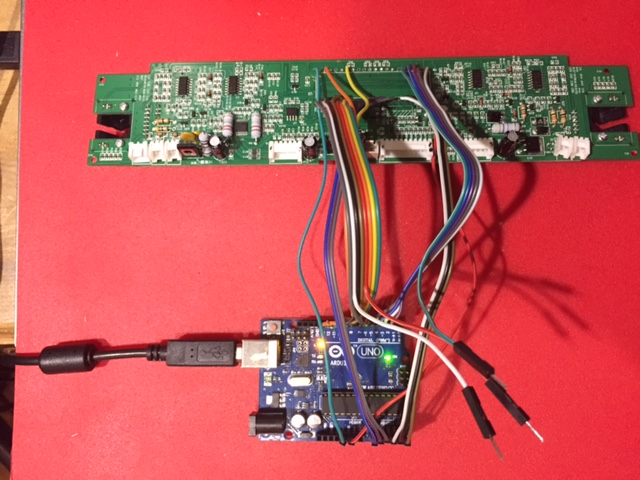
Not much room around the PCB in-situ so I removed the microcontroller, soldered flying leads directly to the PCB and routed them to the indicated arduino pins. I wanted to keep the Rx/Tx pins free so only had 18 pins to play with. It should be possible to multiplex some inputs if needed in the future. Here is the hacked board under test:
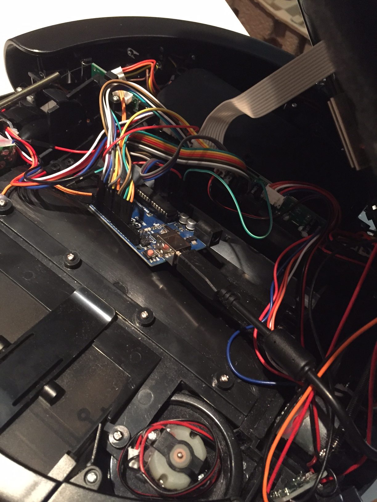
and here it is embedded back in the robot:
The PCB is a tight fit and once the main brush motor is removed there is just enough space for the Arduino to sit in its place.
A simple program was written to exercise the main features. Here is a short video showing the response to bumpers and a quick demo routine that cycles through the LEDs, plays a tune and does a little dance.
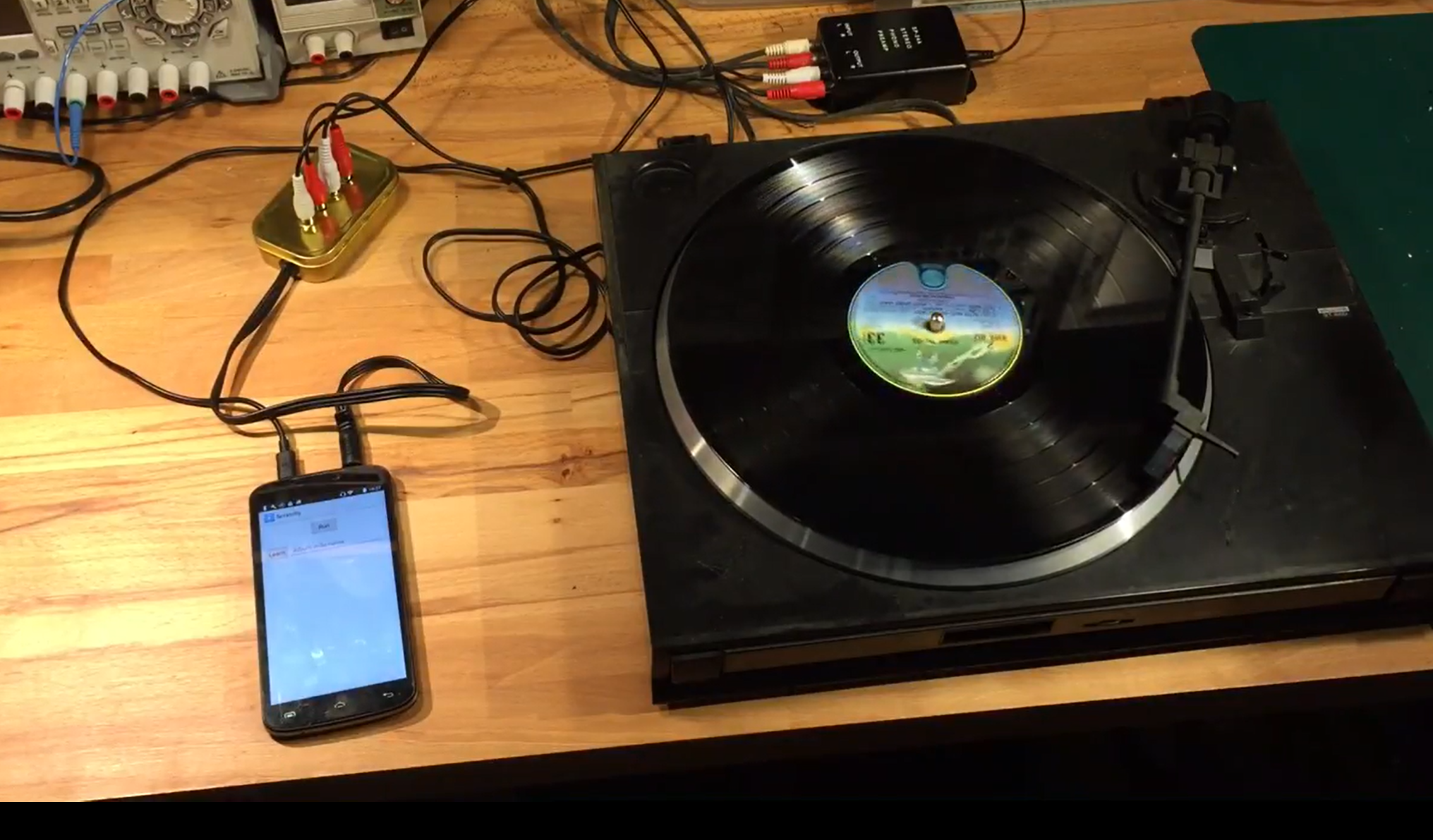
Santa delivered a vinyl record player this year! We had great fun listening to old records from our past. One of the best things about the vinyl experience is the excellent user interface, with touch, feel and even smell. But our record collection is not in the best shape and after a while I missed the less scratchy digital downloads I’d become used to. So I looked for a way to combine the user interface of vinyl with the more predictable quality of mp3 files, and the result wasScratchy!
The idea is to connect the turntable audio output via a black box to an Android app, which listens to what is being played, identifies the album, and plays a digital version of it. At the top level the system looks like this:
Record Player -> Black Box -> Android App -> Amplifier -> Speakers
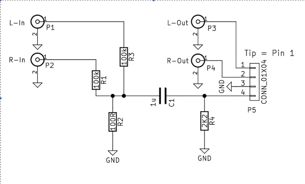
The black box has two main purposes:
to trick the android phone into thinking there is a microphone attached. This just requires a 2.2k resistor from the mic input to ground. Any value resistor above 1k will do, lower values may trigger the phone to mute the audio.
to drop the voltage from line level to mic level and to combine the stereo channels into one. A simple 100:1 resistor divider does the job. This is not needed if the turntable outputs a low level signal.
Here is the schematic:
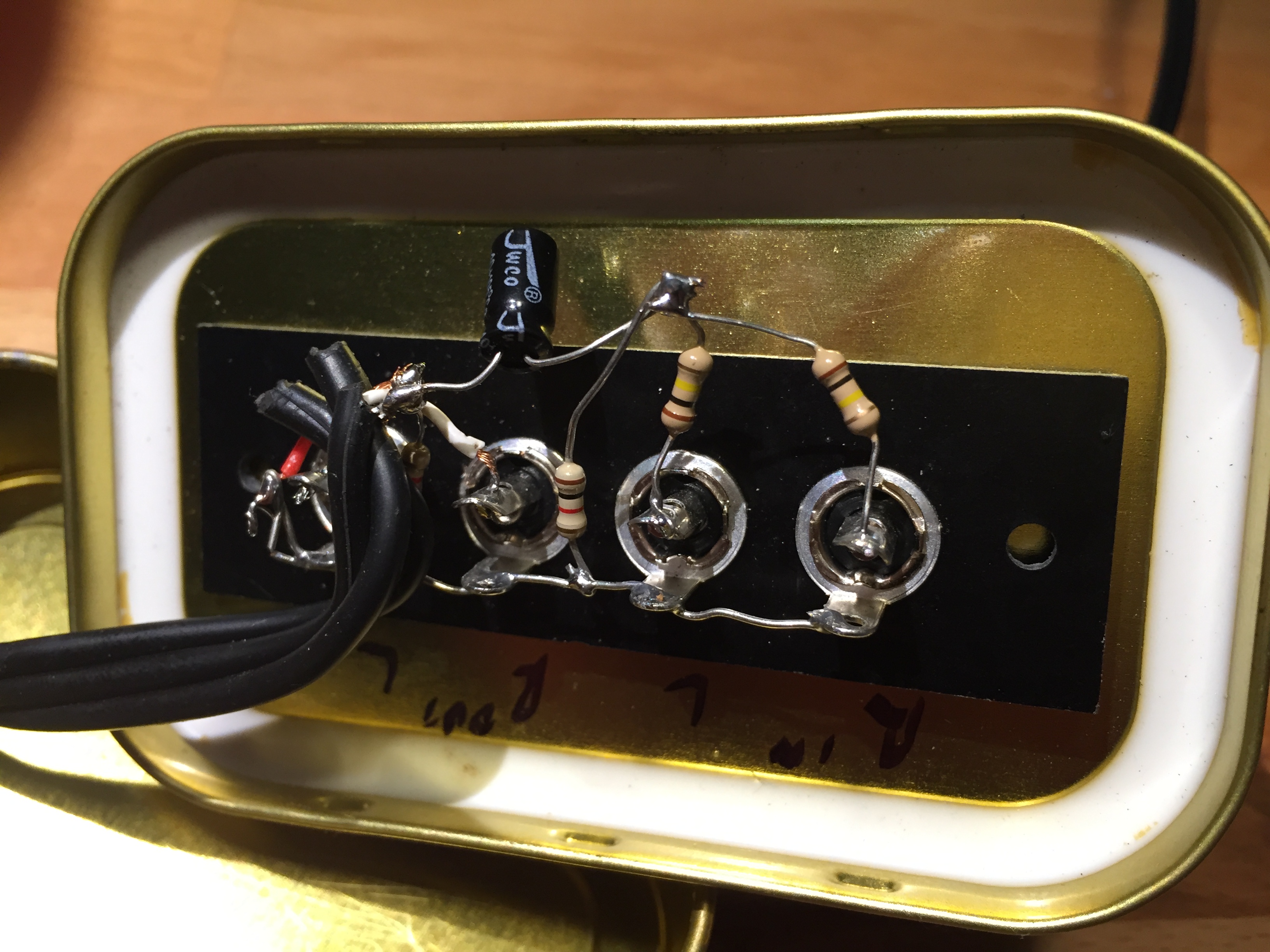
And here is a view inside the black box:
In normal operation the android app runs in a loop as follows:
Listen for a new record being played
Identify the album
Play a digital version of the album
Continue to listen to the turntable output and stop the currently playing album if a period of silence is heard (needle up)
Back to 1
Album identification is done by listening to the first five seconds of audio, fingerprinting it, and then looking up the fingerprint in a database. Fingerprinting is based on an algorithm published by Shazam (ref). The incoming audio is split into 0.1 second samples which are Fourier-transformed, and a set of representative note pairs extracted. See the linked reference for more details on how this works.
The app is trained to recognise new albums by switching to Learn mode, entering the name of the m3u file that it corresponds to, and then playing the album. When audio starts, the app will fingerprint about 7 seconds of it and store the fingerprint together with the m3u filename in a database.
The source album doesn’t need to be of high quality – old scratched records work just as well, as long as the first few seconds can be played and recognised. It is even possible to associate a digital album with a completely different physical record!
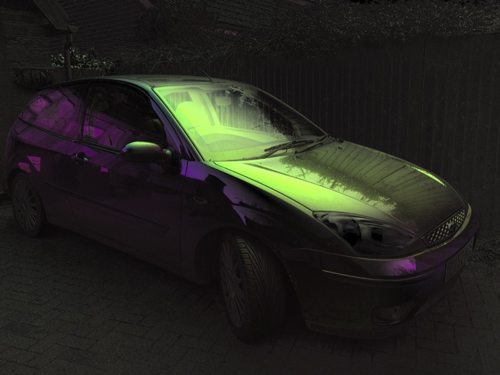
This project describes the construction of an iPhone accessory which allows pictures of polarised light to be captured. It is based on previous work by David Prutchi which should be referred to for more details.
Principles of operation
The device is based on a screen from an auto-darkening welder’s mask purchased on eBay. This is constructed from a liquid crystal panel sandwiched between two cross polarised sheets. When no voltage is applied to the liquid crystal it rotates incident light by 90 degrees and so the light passes through fairly unimpeded. When about 5V is applied the rotation drops to zero degrees and blocks the light.
Removing one of the polarised sheets produces a voltage-controlled polariser. Prutchi showed that there exists a voltage between 0 and 5V where the incident light is rotated by 45 degrees. By taking three images at 0, 45 and 90 degrees the degree and angle of polarisation can be determined for each pixel in the scene and visualised.
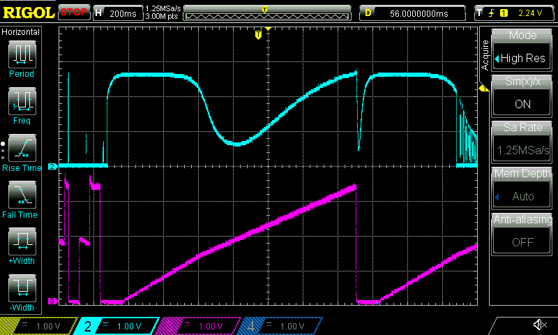
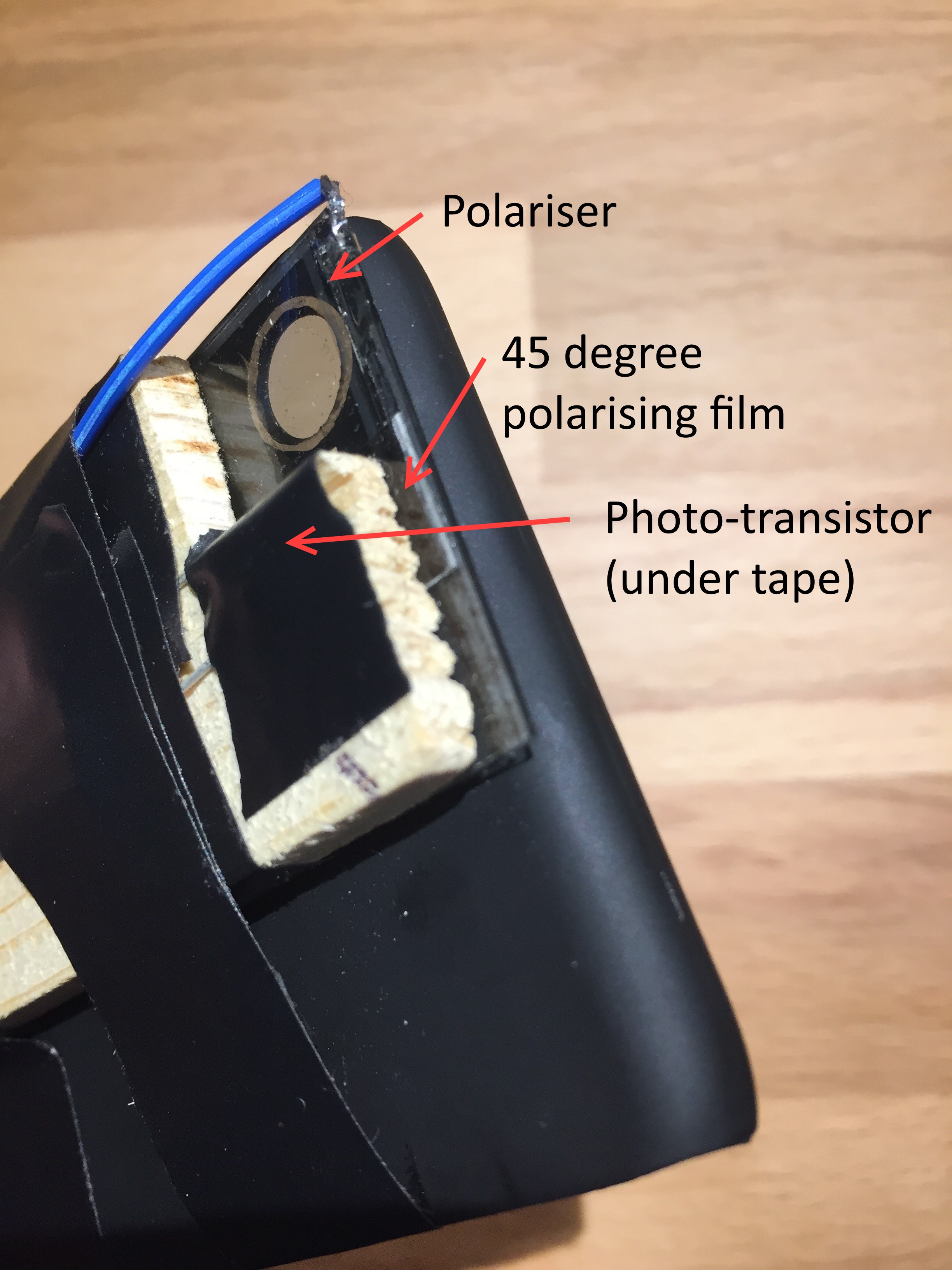
The precise voltage at which 45 degree rotation occurs varies over time so a way is need to calibrate the polariser. In this design a piece of polarising sheet is placed at 45 degrees and light from the iPhone’s flash-light is shone through and detected with a photo-transistor. By varying the voltage across the polariser, a minima in transmitted light occurs when the 45 degree polarisers cross. This minima can be detected and used to set the corresponding 45 degree voltage reference.
Bottom trace – polariser voltage. Top trace – light detected by the photo-transistor. A clear minima can be seen.
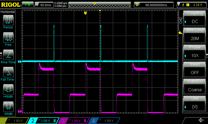
The iPhone’s flash-light is also used to synchronise the change in polarisation with the image taking. The iPhone blinks the flash-light after every three images have been taken. The device uses this flash to reset the 0,45,90 sequence to a known state.
Top trace (blue) – light pulses from photo-transistor. Bottom trace (purple) – synchronised voltage applied to the polariser.
Firmware
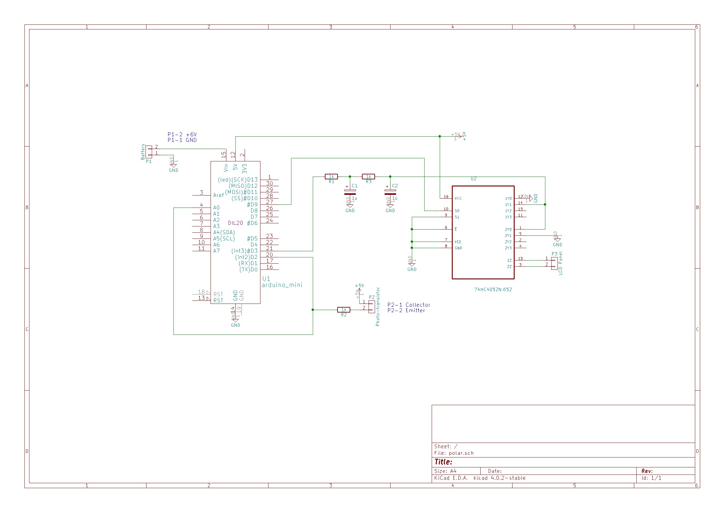
An Arduino is used to control the polariser. A photo-transistor located facing the iPhone’s flash-light LED is connected to both an external interrupt pin and an analog pin. Short pulses on the LED cause interrupts in the Arduino code which are used to synchronise the polariser. Long pulses on the LED cause the Arduino to enter calibration mode.
The time interval between synchronisation pulses is continuously measured and divided into three equal parts. On receiving a synchronisation pulse the voltage is set to 0V for one part, to the 45 degree voltage for one part and finally to 5V for one part.
Voltage for the polariser is supplied from an Arduino PWM output pin. To get a reasonably stable output the PWM frequency was increased to 32 kHz and smoothed with a second order RC filter.
The liquid crystal display will be damaged by a constant DC voltage so a CMOS switch is used to alternate the polarity. A 2 kHz square wave generated from a free running Arduino timer is used to drive the switching.
Hardware
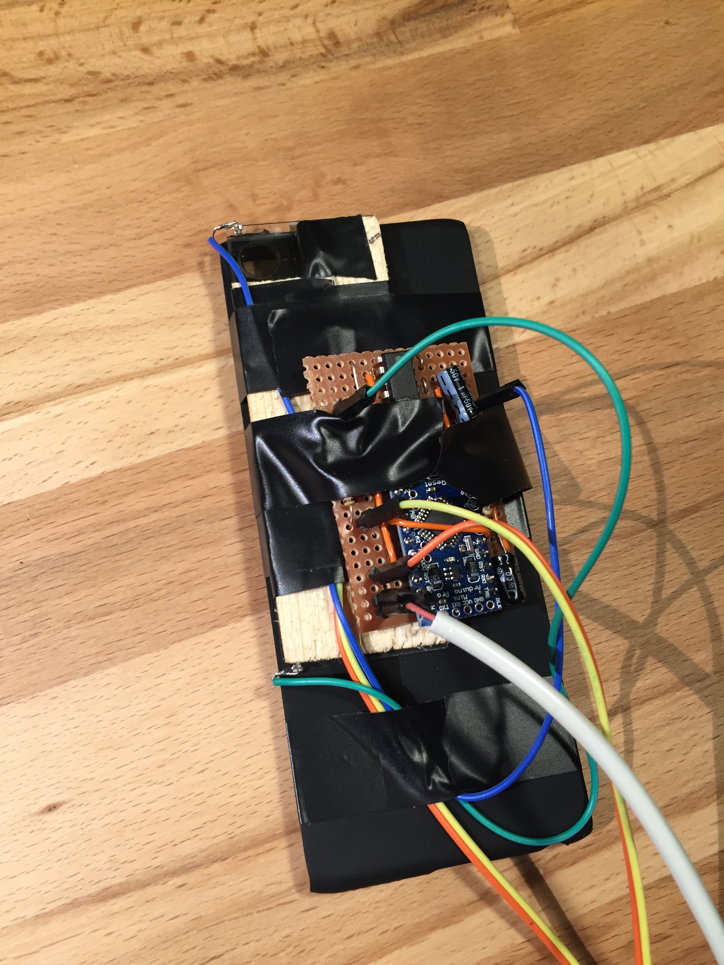
The polariser was mounted on a cheap iPhone cover so that it covered the camera lens and the flash-light led. The photo-transistor was mounted in a strip of wood and taped to the polariser facing the iPhone flash light. For calibration a small strip of polarising film was cut at a 45 degree angle and inserted between the photo-transistor and the polariser. The circuit was made up on a scrap of strip-board. A separate battery pack was used to power the device.
Assembled device
Camera head detail
iPhone App
The iPhone app is responsible for the UI and image processing. It is written in Swift.
Image frames are continuously captured from the camera. The time for three images to be captured is measured. A minimum of 60 ms per image is required and if needed intermediate frames are skipped to allow the polariser enough time to change between states. The flash-light is blinked after every 3 images to synchronise the polarisation. The blink is delayed by a variable amount to shift the alignment of frames to the changes in polarisation. A slider is provided to alter the alignmentdelay.
When three images have been received corresponding to 0, 45 and 90 degrees polarisation, they are processed to generate a representation of the scene which is displayed on the screen. Custom GL kernels are used to solve the Stokes equations and generate either an RGB or HSV visualisation of polarisation parameters. These calculations run on the phone’s GPU and so are easily able to keep up with the camera’s frame rate.
A “Calibrate” button turns on the flash-light for 2 seconds. This triggers the Arduino to run a calibration of the 45 degree voltage level, and provides the light to do so.
A selector allows a choice between RGB or HSV visualisation.
A “Shutter” button takes a picture by saving the latest processed image to the camera roll.
Full source code for the Arduino and iPhone is available here.
Example Images
Laptop cover illuminated at a shallow angle from rear showing horizontal polarisation (HSV)
CD jewel case in front of laptop screen showing stress patterns (HSV)
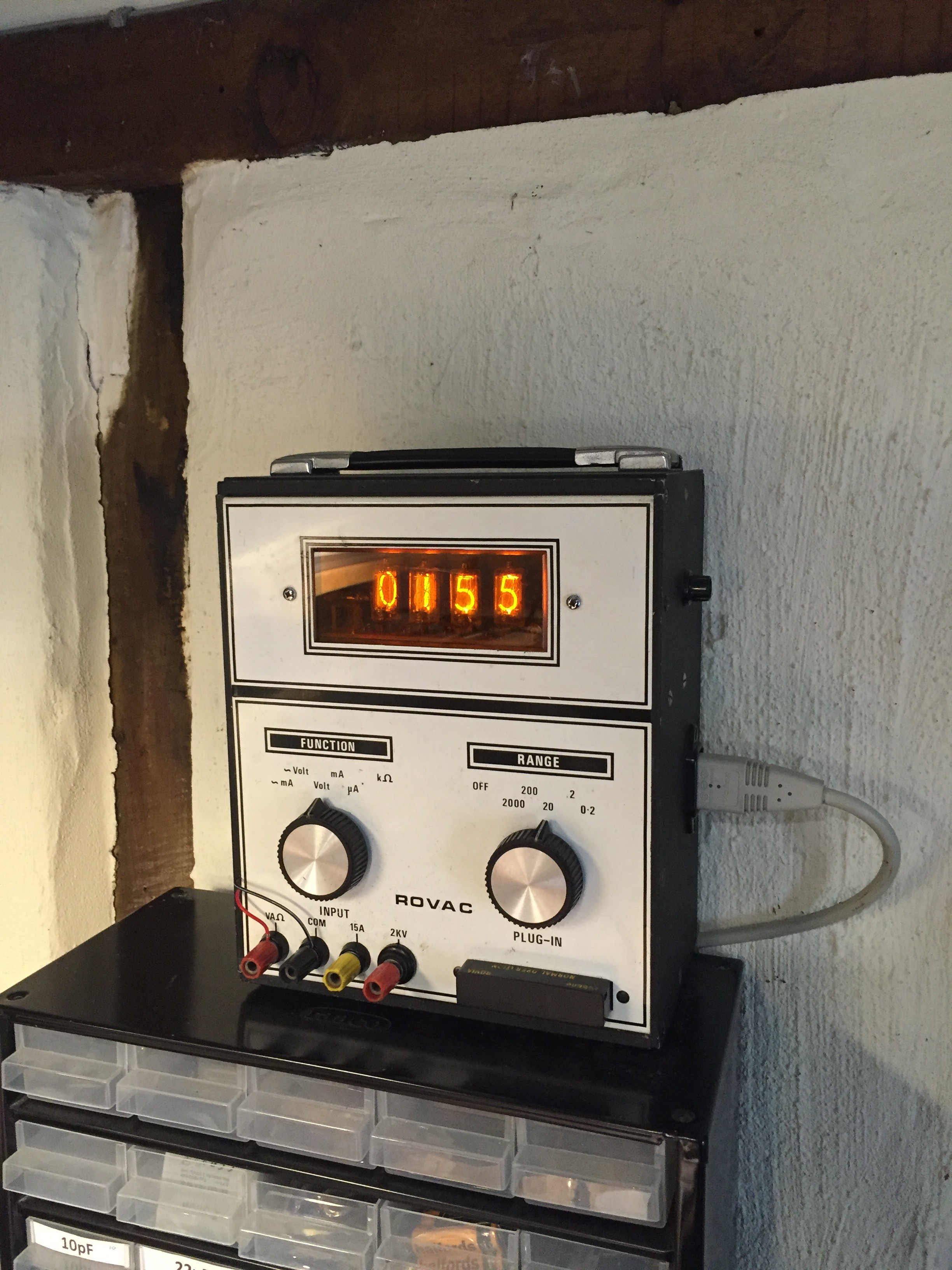
I recently acquired a vintage nixie tube multi-meter on eBay, with the not so original idea of converting it into a clock.
However, rather than hack around with the internal circuitry, I decide to see if I could keep the meter intact and use the existing voltmeter functionality to display time. The basic idea is to send the meter a voltage corresponding to the time, so e.g. 12:45 becomes 12.45V. The meter has a 20V range which displays a fixed 2 decimal places which suits my purpose just fine. Unfortunately there is a hard limit to 20V on this range so a full 24 hour clock is not possible, but a 12 hour clock and maybe a 20 hour clock are.
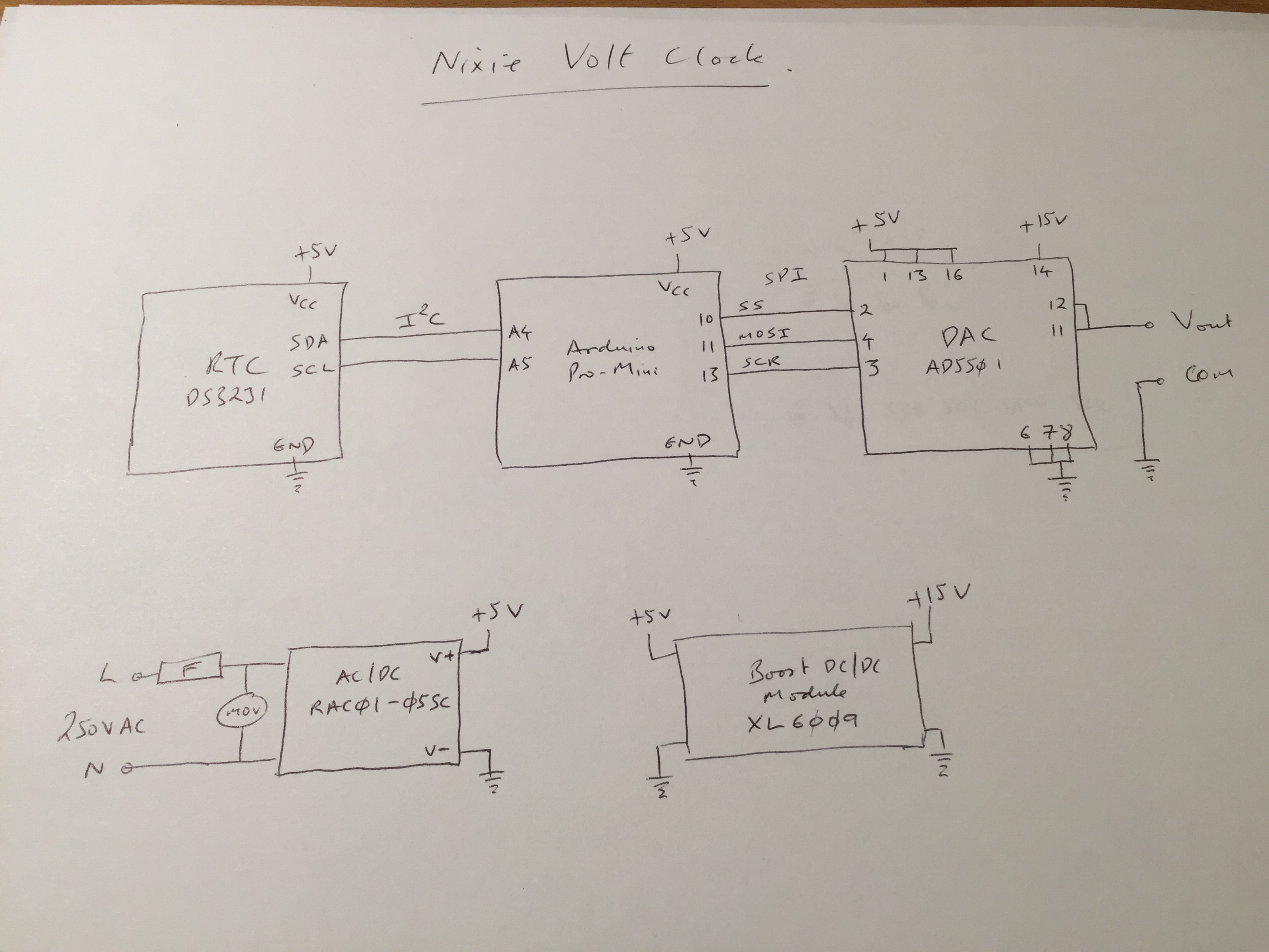
The high level schematic is:
RTC -> Arduino -> DAC ->Multi-meter
Each minute on the display corresponds to 10mV so the DAC must be at least this resolution. I used an AD5501 which has 12bit resolution and can work at up to 60V. For my needs I used the 30V range which works out at 7.3mV per bit, just enough. This DAC also has an integrated voltage reference which reduces the component count. It comes in a TSSOP package so was soldered onto a breakout board for easier prototyping.
For the RTC I used a DS3231 module. This is accurate to about 1 min/year and has a battery backup. It can be controlled from the arduino over an I²C bus.
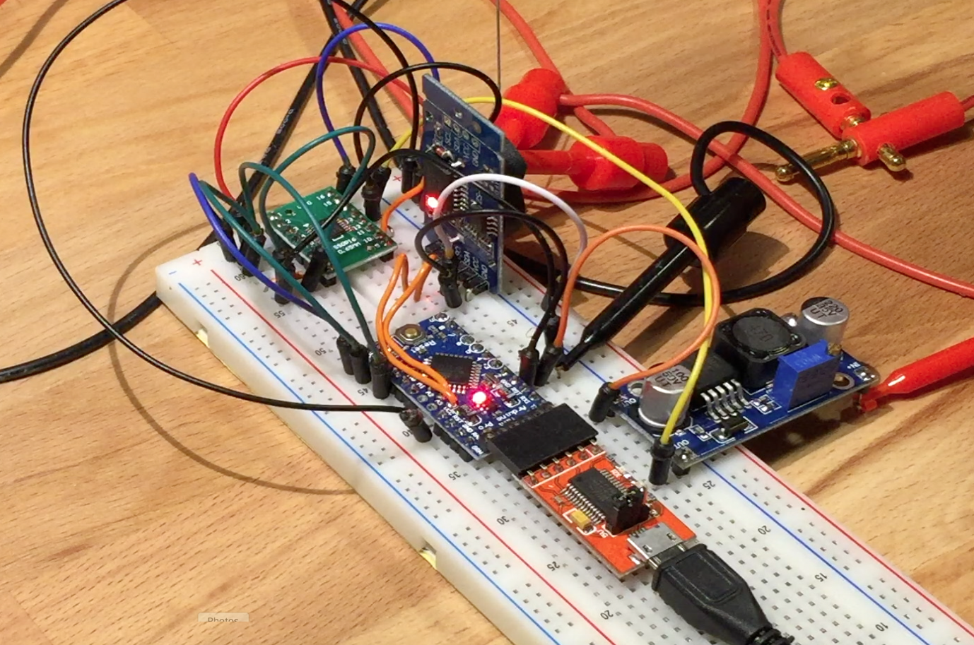
The Arduino runs a simple program which at every new minute gets the current time, calculates the required voltage for the time, offsets it by a calibration factor and sends it to the DAC. The program also accepts a few commands over the serial port to calibrate the display and set the current time.
Here is everything running on a breadboard:
For power, rather than tap into the internal multi-meter power buses I hooked up a simple 240VAC/5VDC module with a cheap Chinese boost converter to give 15V for the analogue power.
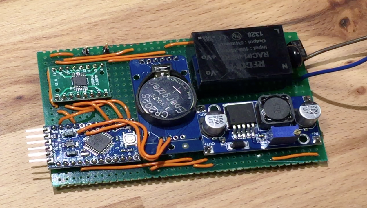
The meter has space inside for a battery so there was no need to miniaturise the component layout and I just wired the modules together on a bit of strip-board, fixed it to an insulating base and popped it into the meter.


![IMG_6002[1]](https://ynformatics.com/wp-content/uploads/2016/03/IMG_60021.jpg)