This project describes the construction of an iPhone accessory which allows pictures of polarised light to be captured. It is based on previous work by David Prutchi which should be referred to for more details.
Principles of operation
The device is based on a screen from an auto-darkening welder’s mask purchased on eBay. This is constructed from a liquid crystal panel sandwiched between two cross polarised sheets. When no voltage is applied to the liquid crystal it rotates incident light by 90 degrees and so the light passes through fairly unimpeded. When about 5V is applied the rotation drops to zero degrees and blocks the light.
Removing one of the polarised sheets produces a voltage-controlled polariser. Prutchi showed that there exists a voltage between 0 and 5V where the incident light is rotated by 45 degrees. By taking three images at 0, 45 and 90 degrees the degree and angle of polarisation can be determined for each pixel in the scene and visualised.
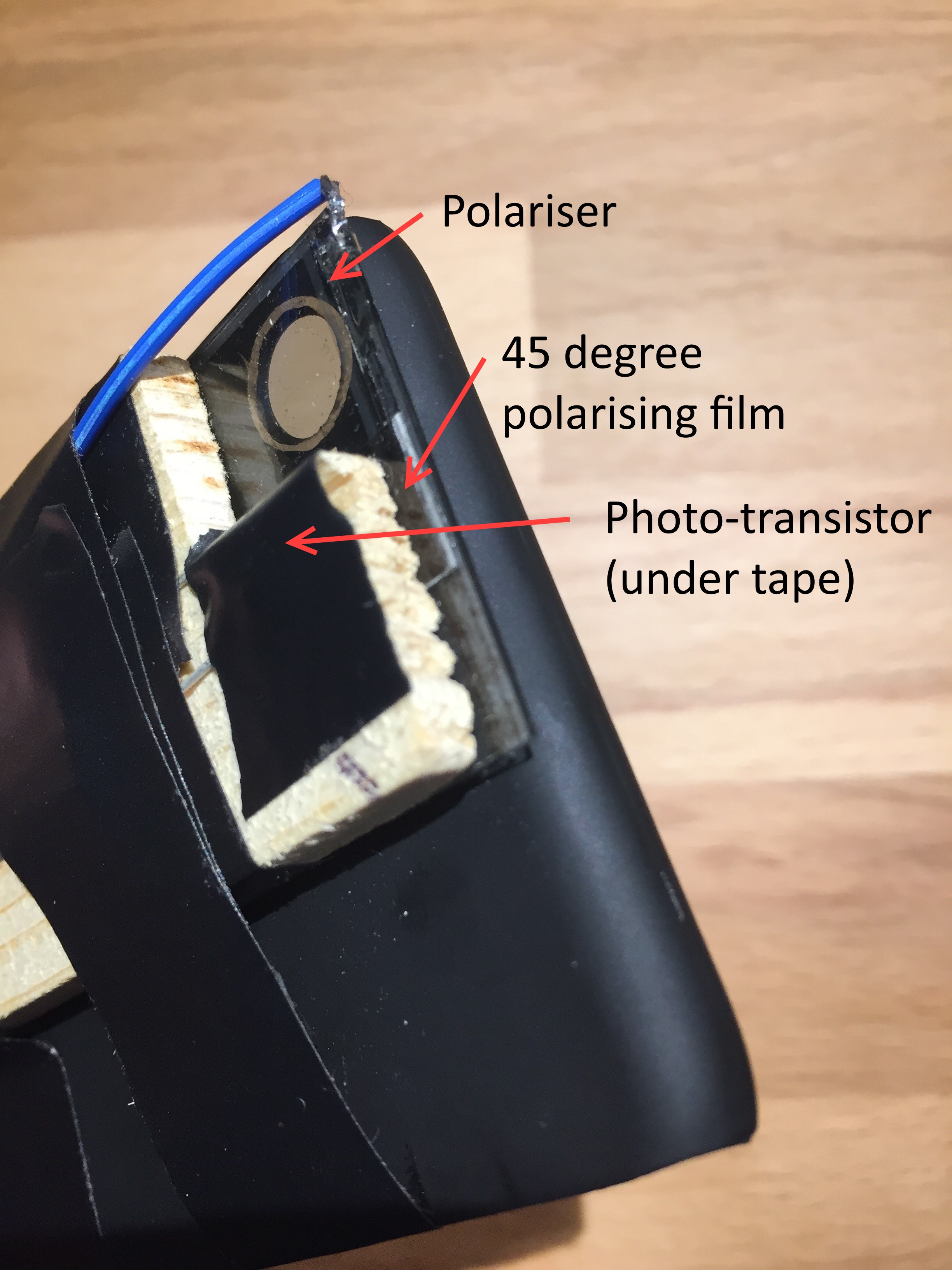
The precise voltage at which 45 degree rotation occurs varies over time so a way is need to calibrate the polariser. In this design a piece of polarising sheet is placed at 45 degrees and light from the iPhone’s flash-light is shone through and detected with a photo-transistor. By varying the voltage across the polariser, a minima in transmitted light occurs when the 45 degree polarisers cross. This minima can be detected and used to set the corresponding 45 degree voltage reference.
The iPhone’s flash-light is also used to synchronise the change in polarisation with the image taking. The iPhone blinks the flash-light after every three images have been taken. The device uses this flash to reset the 0,45,90 sequence to a known state.
Firmware
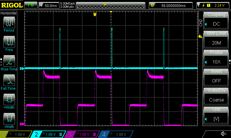
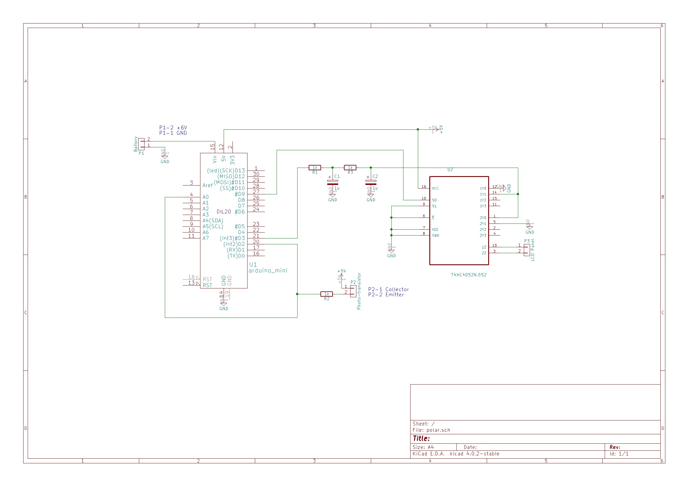
An Arduino is used to control the polariser. A photo-transistor located facing the iPhone’s flash-light LED is connected to both an external interrupt pin and an analog pin. Short pulses on the LED cause interrupts in the Arduino code which are used to synchronise the polariser. Long pulses on the LED cause the Arduino to enter calibration mode.
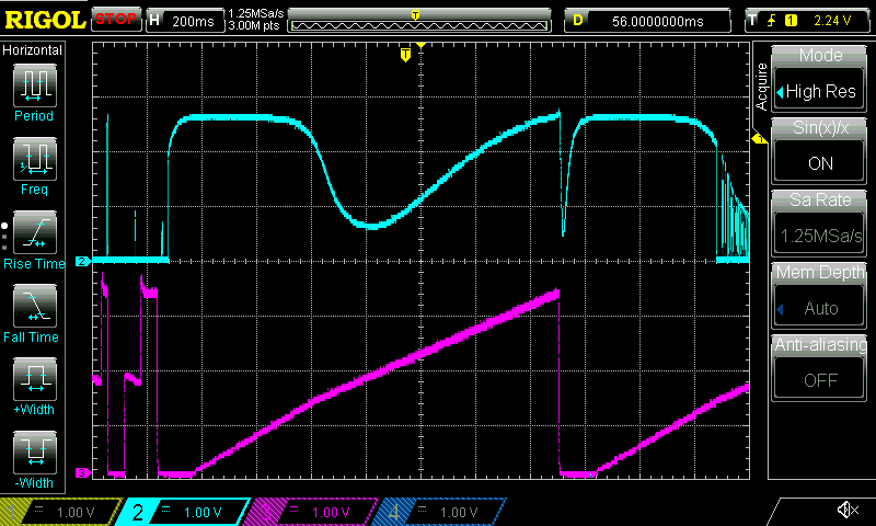
The time interval between synchronisation pulses is continuously measured and divided into three equal parts. On receiving a synchronisation pulse the voltage is set to 0V for one part, to the 45 degree voltage for one part and finally to 5V for one part.
Voltage for the polariser is supplied from an Arduino PWM output pin. To get a reasonably stable output the PWM frequency was increased to 32 kHz and smoothed with a second order RC filter.
The liquid crystal display will be damaged by a constant DC voltage so a CMOS switch is used to alternate the polarity. A 2 kHz square wave generated from a free running Arduino timer is used to drive the switching.
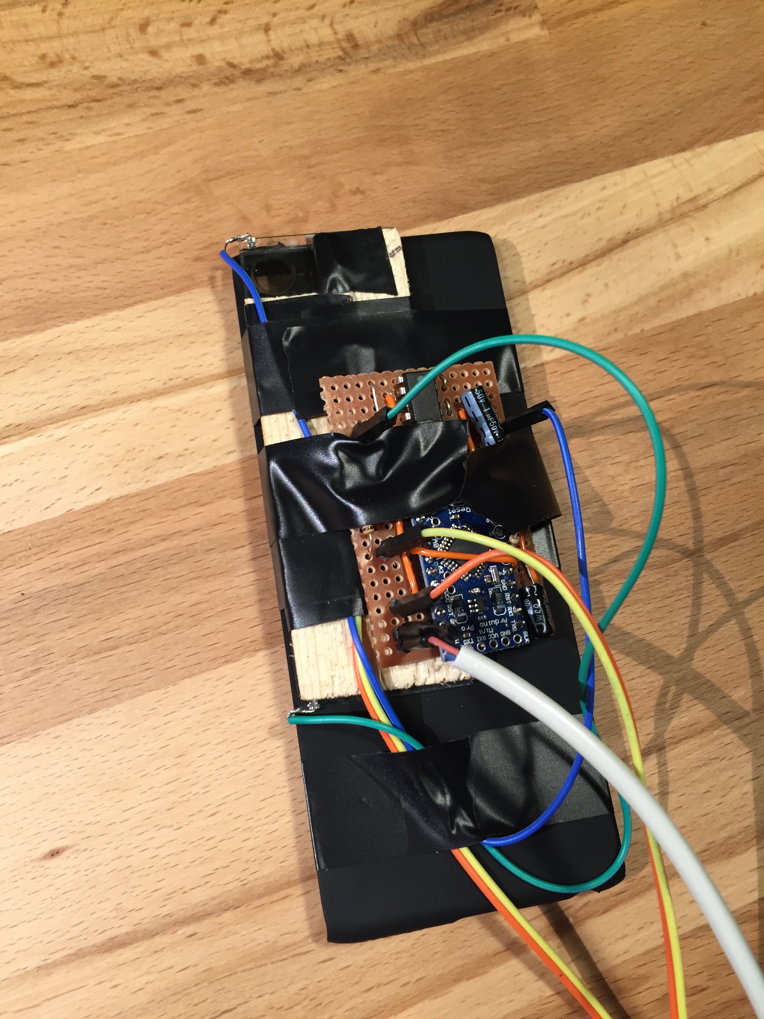
Hardware
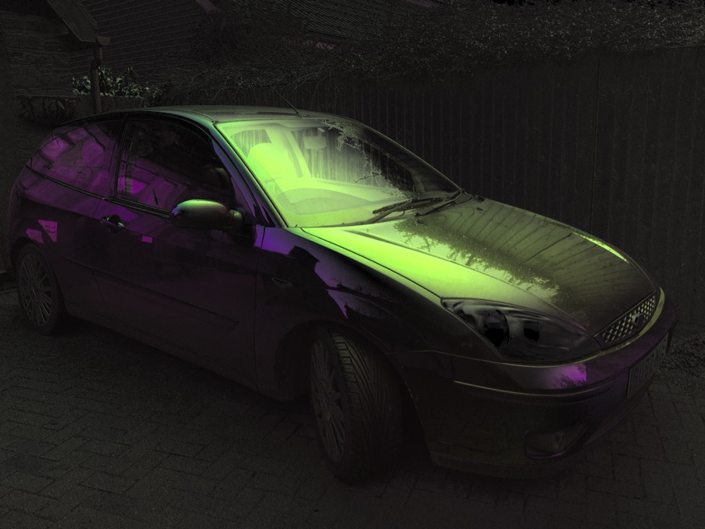
The polariser was mounted on a cheap iPhone cover so that it covered the camera lens and the flash-light led. The photo-transistor was mounted in a strip of wood and taped to the polariser facing the iPhone flash light. For calibration a small strip of polarising film was cut at a 45 degree angle and inserted between the photo-transistor and the polariser. The circuit was made up on a scrap of strip-board. A separate battery pack was used to power the device.
iPhone App
The iPhone app is responsible for the UI and image processing. It is written in Swift.
Image frames are continuously captured from the camera. The time for three images to be captured is measured. A minimum of 60 ms per image is required and if needed intermediate frames are skipped to allow the polariser enough time to change between states. The flash-light is blinked after every 3 images to synchronise the polarisation. The blink is delayed by a variable amount to shift the alignment of frames to the changes in polarisation. A slider is provided to alter the alignmentdelay.
When three images have been received corresponding to 0, 45 and 90 degrees polarisation, they are processed to generate a representation of the scene which is displayed on the screen. Custom GL kernels are used to solve the Stokes equations and generate either an RGB or HSV visualisation of polarisation parameters. These calculations run on the phone’s GPU and so are easily able to keep up with the camera’s frame rate.
A “Calibrate” button turns on the flash-light for 2 seconds. This triggers the Arduino to run a calibration of the 45 degree voltage level, and provides the light to do so.
A selector allows a choice between RGB or HSV visualisation.
A “Shutter” button takes a picture by saving the latest processed image to the camera roll.
Full source code for the Arduino and iPhone is available here.
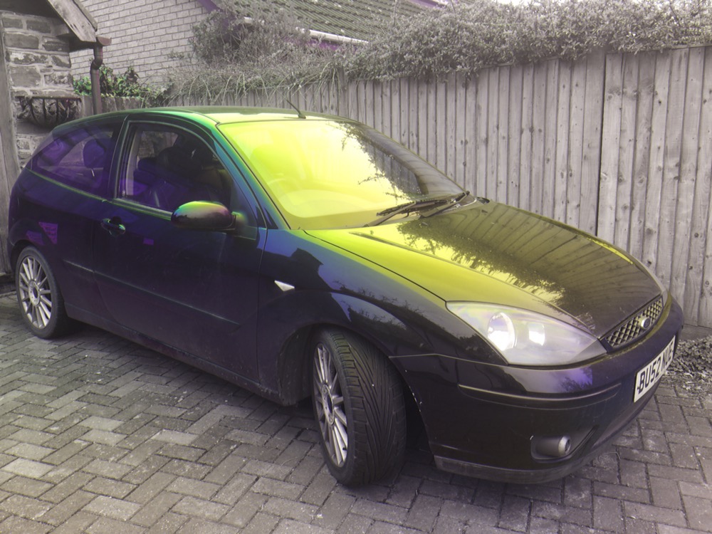
Example Images
![IMG_6002[1]](https://ynformatics.com/wp-content/uploads/2016/03/IMG_60021.jpg)

One thought on “iPhone Polarisation Camera”