Part 2 (software) now available
I needed a robot platform for a project and bought a Vileda A3 cleaning robot cheaply from ebay, advertised as not working but a new battery fixed that! (Battery for Vileda M-488a fits this A3 model)

Opening it up:
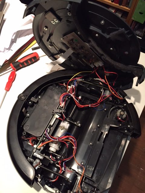
we find the expected motors for the wheels, fan, main brush and edge brush. The wheels are equipped with optical encoders. Other sensors include the left and right bumpers, wheel drop switches and cliff detectors. The top lid holds three buttons and a red and green LED. There is a 360 IR reflector installed but this is not populated with a detector.
There is a self-contained NiMH battery charger board under the top lid:
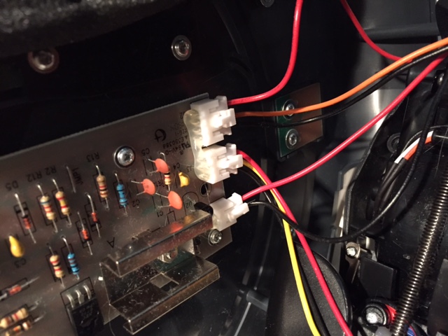
Rather than totally replace the existing PCB I decided to just replace the microcontroller (an 8051 clone) so I could keep the existing motor drivers, connectors etc
After a bit of reverse engineering I came up with the following PCB pin assignments:
| μC Pin | Function | Arduino Pin/Dir | Notes |
|---|---|---|---|
| 1 | Right Bumper | D6 In | HIGH on bump |
| 2 | Over current | In | Unused |
| 3 | |||
| 4 | Right wheel forward | D10 Out PWM | IN1 |
| 5 | Right wheel backward | D9 Out PWM | IN2 |
| 6 | |||
| 7 | Fan & Side brush motor | Out | Unused |
| 8 | Wheels up | D13 In | All 3 wheels OR’ed |
| 9 | L switch | D12 In | LOW when pressed |
| 10 | L switch LED | D11 Out | Active LOW |
| 11 | |||
| 12 | M switch | A0 In | LOW when pressed |
| 13 | S switch | A1 In | LOW when pressed |
| 14 | Green LED | A2 Out | Active LOW |
| 15 | Red LED | A3 Out | Active LOW |
| 16 | M switch LED | A4 Out | Active LOW |
| 17 | S switch LED | A5 Out | Active LOW |
| 18 | |||
| 19 | |||
| 20 | GND | ||
| 21 | Left wheel forward | D3 Out PWM | IN4 |
| 22 | Left wheel backwards | D5 Out PWM | IN3 |
| 23 | Left bumper | D2 In | HIGH on bump |
| 24 | Speaker | D4 Out | |
| 25 | |||
| 26 | Main brush motor | Out | Unused |
| 27 | |||
| 28 | |||
| 29 | |||
| 30 | |||
| 31 | |||
| 32 | |||
| 33 | |||
| 34 | |||
| 35 | Left wheel encoder | D7 In | |
| 36 | |||
| 37 | |||
| 38 | |||
| 39 | Right wheel encoder | D8 In | |
| 40 | +5V regulated |
N.B. pin 9 was wired as an 8051 interrupt circuit so I modified PCB to make it a simple switched input (removed C23 and R89 and wired J7 pin 4 directly to μC pin 9).
I didn’t need the cliff sensors so didn’t trace those out.
The motor driver chip is an Allegro A4954 dual 2A/40V h-bridge. Current limit is pre-set. Pins IN1-IN4 of this chip are routed to the microcontroller.
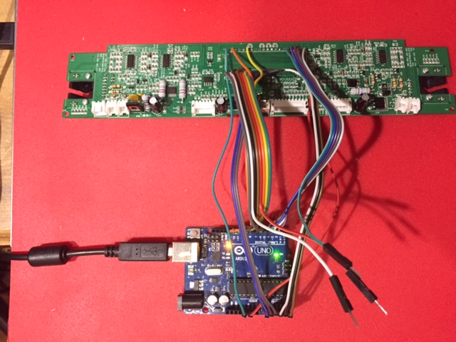
Not much room around the PCB in-situ so I removed the microcontroller, soldered flying leads directly to the PCB and routed them to the indicated arduino pins. I wanted to keep the Rx/Tx pins free so only had 18 pins to play with. It should be possible to multiplex some inputs if needed in the future. Here is the hacked board under test:
and here it is embedded back in the robot:
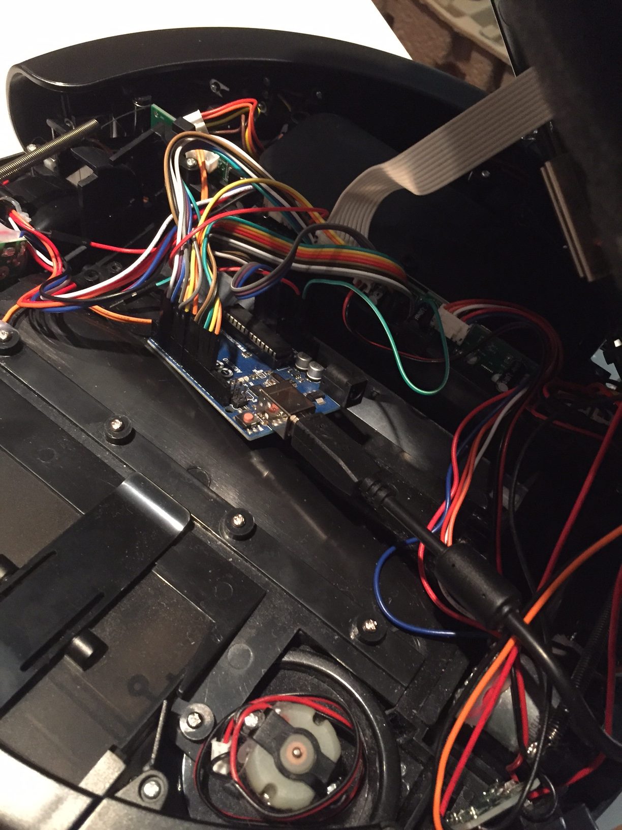
The PCB is a tight fit and once the main brush motor is removed there is just enough space for the Arduino to sit in its place.
A simple program was written to exercise the main features. Here is a short video showing the response to bumpers and a quick demo routine that cycles through the LEDs, plays a tune and does a little dance.
It is so cute!
Thanks!
Hello,
What is the startup voltage for the unmodified A3?
I have made a 4 cell LiIon battery with BMS board into it. Charging is ok.
But as soon as i pull out plug and hit a S, M or L button it is starting a control sequence but wont start up, flash red led. Battery shows 16,89V.
Hi,
Just switched mine on and it starts OK after a year on the shelf. Battery reads 14.9V (it’s a 14.4V NiMh pack).
Hope that helps!