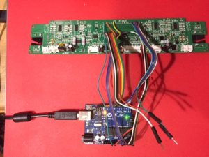
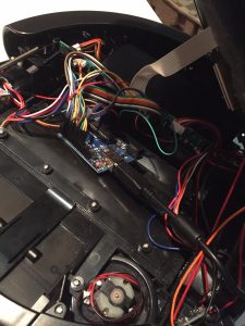
Part 1 described the hardware portion of this project. TL;DR: the existing microprocessor was replaced with an Arduino.
Part 2 covers the low level robot control and iRobot Create emulation software.
A couple of hardware modifications have been made since part 1 was written:
- The Arduino Uno was replaced by a Nano. This is not only a lot smaller but also has a couple of extra IO ports.
- A battery voltage sensor was added in the form of a simple 4:1 resistor divider.
Thearduino pin mapping is now:
| μC Pin | Function | Arduino Pin/Dir | Notes |
|---|---|---|---|
| 1 | Right Bumper | D6 In | HIGH on bump |
| 2 | Over current | In | Unused |
| 3 | |||
| 4 | Right wheel forward | D10 Out PWM | IN1 |
| 5 | Right wheel backward | D9 Out PWM | IN2 |
| 6 | |||
| 7 | Fan & Side brush motor | Out | Unused |
| 8 | Wheels up | D11 In | All 3 wheels OR’ed |
| 9 | L switch | D12 In | LOW when pressed |
| 10 | L switch LED | D13 Out | Active LOW |
| 11 | |||
| 12 | M switch | A6 In | LOW when pressed |
| 13 | S switch | A7 In | LOW when pressed |
| 14 | Green LED | A2 Out | Active LOW |
| 15 | Red LED | A3 Out | Active LOW |
| 16 | M switch LED | A4 Out | Active LOW |
| 17 | S switch LED | A5 Out | Active LOW |
| NC | Battery Voltage | A0 In | Via 4:1 divider |
| 19 | |||
| 20 | GND | GND | |
| 21 | Left wheel forward | D3 Out PWM | IN4 |
| 22 | Left wheel backwards | D5 Out PWM | IN3 |
| 23 | Left bumper | D2 In | HIGH on bump |
| 24 | Speaker | D4 Out | |
| 25 | |||
| 26 | Main brush motor | A1 Out | Unused |
| 27 | |||
| 28 | |||
| 29 | |||
| 30 | |||
| 31 | |||
| 32 | |||
| 33 | |||
| 34 | |||
| 35 | Left wheel encoder | D7 In | |
| 36 | |||
| 37 | |||
| 38 | |||
| 39 | Right wheel encoder | D8 In | |
| 40 | +5V regulated | 5V |
For the software it was decided to emulate an iRobot Create 2. This has a documented API (iRobot Create 2 Open Interface) so all design decisions have already been made. Also, because this is a popular platform, third party software exists to directly control the robot and a driver for ROS integration is available.
Not all of the Open Interface commands were implemented, just those required for motor control, odometry and common sensors. The source code can be extended as needed. Some constants may need changing.
The code is straight forward in operation:
- The serial port is monitored for any incoming commands. The commands are parsed and executed which results in motors running, sensor data being returned or robot state being updated.
- Wheel encoder pulses are accumulated via two interrupt handlers
- Every 15ms the internal state is updated. Sensor data is streamed out if requested. If the robot is moving, the motor power is updated. In normal driving mode (velocity and radius specified) a PID controller for average velocity is cascaded with another PID controller to keep the wheel speeds in the required ratio for the specified turn radius. In “Direct” driving mode (velocity of each wheel specified), two PID controllers, one for each wheel, are used to keep the velocities at the requested values
- The Arduino PID Library is used with some modifications including bias value support
Full code available on GitHub here.
To verify compatibility the code was tested with the following:
- The Create.1.0.1.2.exe program from here. (If running on Windows 10 need to run as administrator). Local copy here.
- The create_autonomy ROS driver
