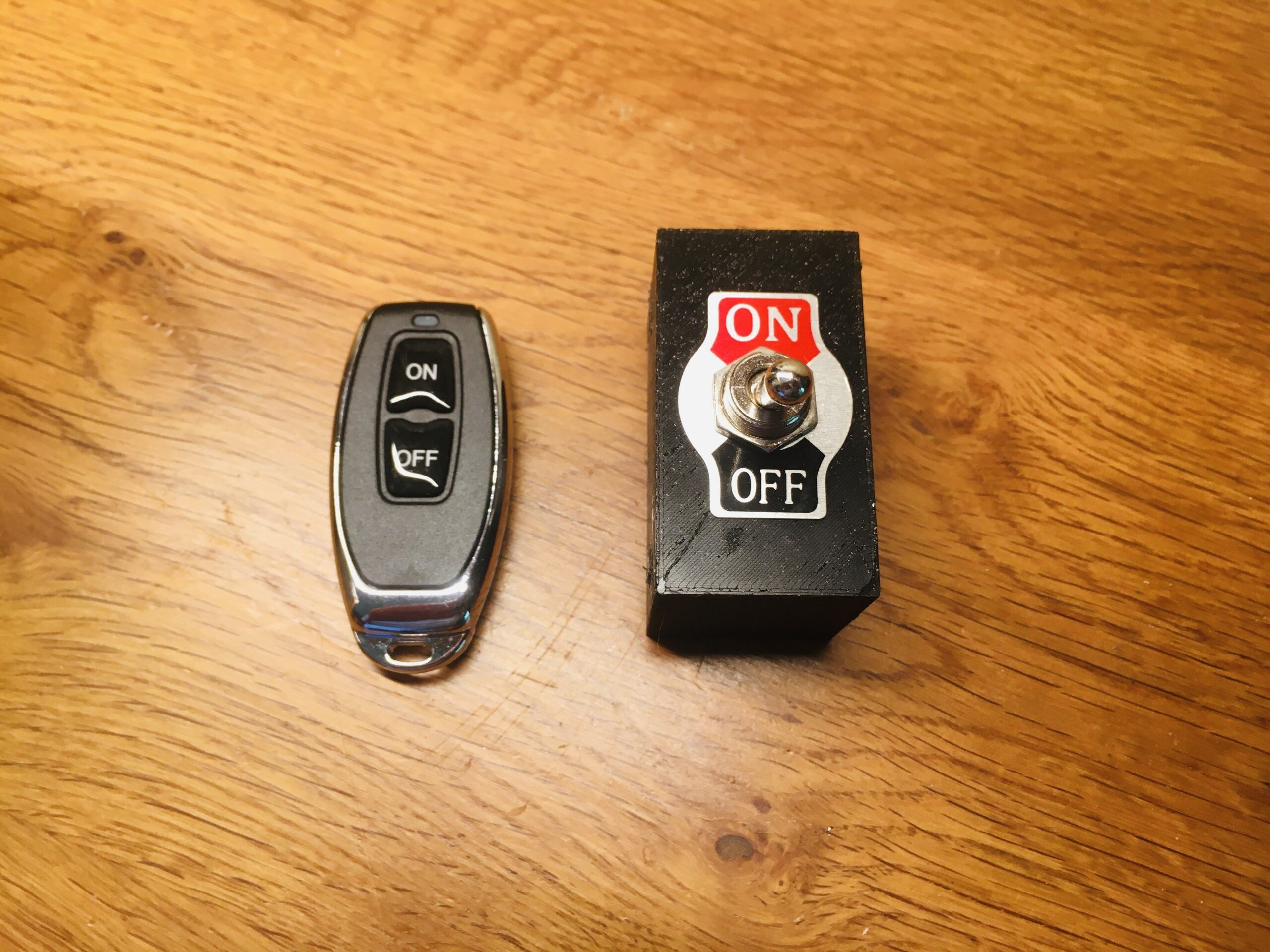
I have a wireless switch with a key fob style remote control. It works fine but the use of a toggle switch has been mandated 😉
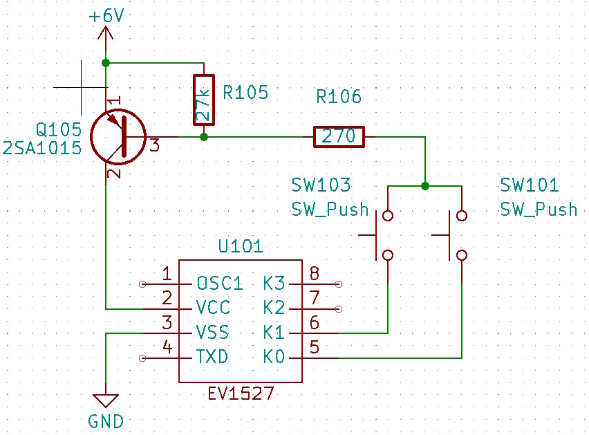
First task is to reverse engineer the remote control. It uses the common EV1527 encoder chip and relies on the data pins’ internal pulldowns to sink current when a button is pressed. This turns on the PNP transistor and powers on the chip.
The device operates off two coin cell batteries and I wanted to keep the device low power. The modified circuit for toggled operation is below:
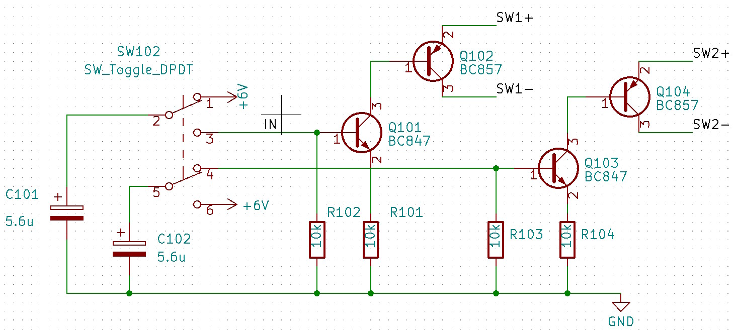
As shown C101 will charge to +6V. When toggled, Q101 will turn on followed by Q102. C101 will discharge via R102 so after a delay Q101 and Q102 will turn off. Q102 is connected across the push button contacts so this will mimic a short button press. At the same time C102 is being charged ready for the next toggle.
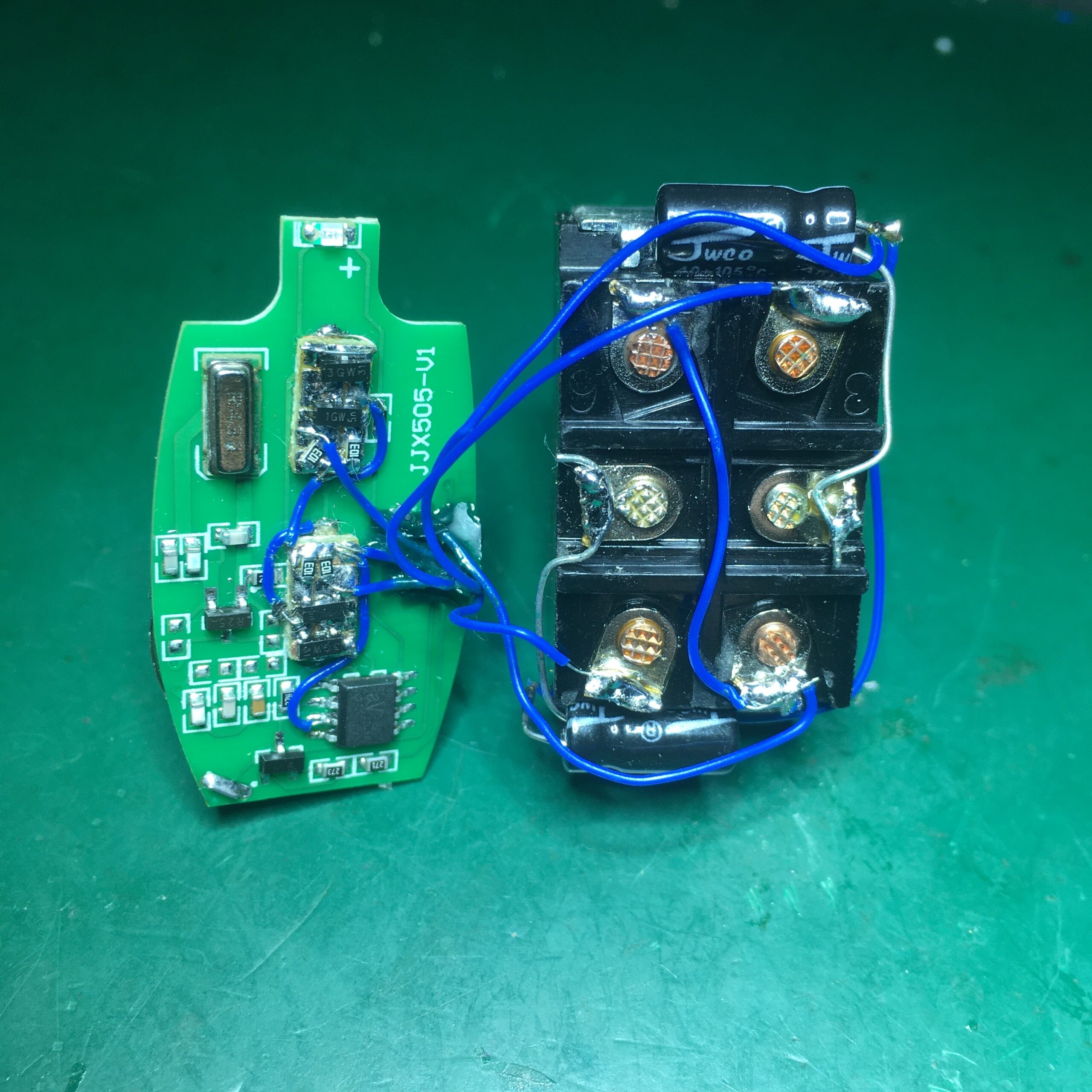
I made up the circuit on some copper clad board and wired it up to the toggle switch
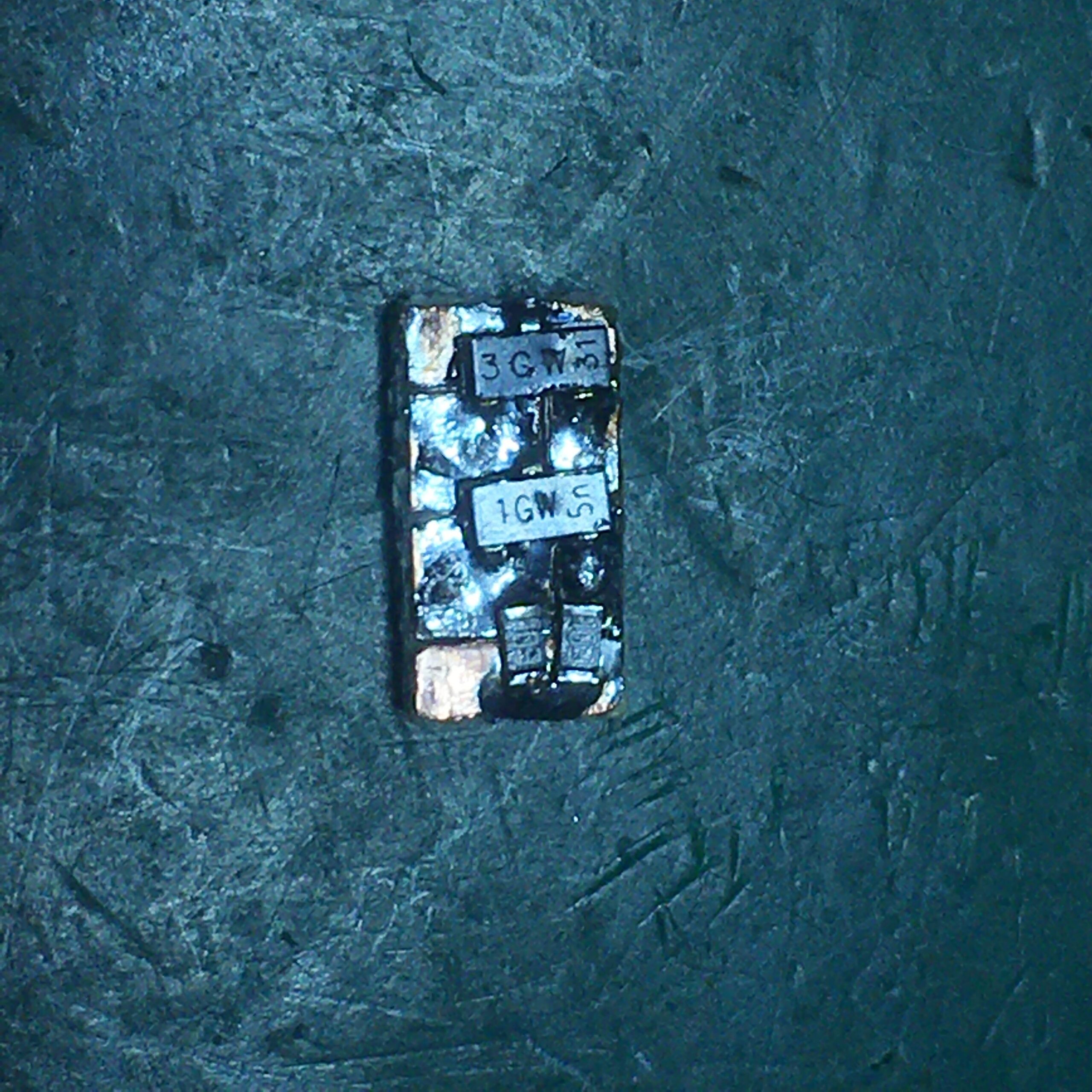
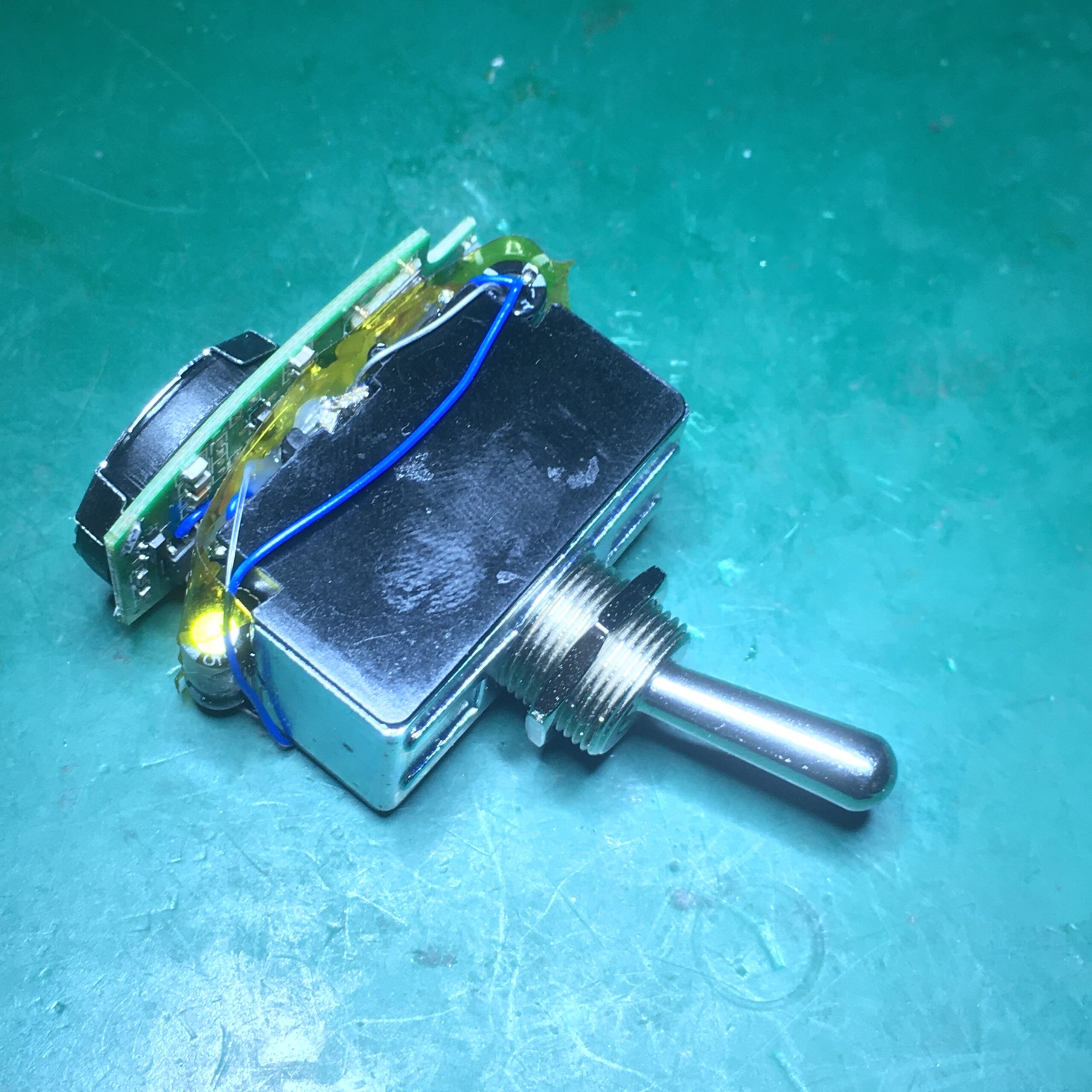
Followed by some Kapton tape and hot glue sandwich to give a compact result:
A 3d printed case completes the job: