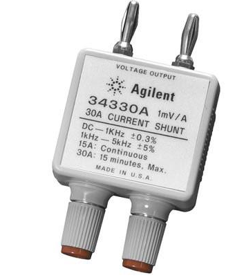
I needed a precision current shunt to calibrate a recently fixed E3631A power supply. The Agilent 34330A looks nice and is colour coordinated, but at $108 seemed a bit pricey for a resistor in a box.
So let’s make a DIY clone…
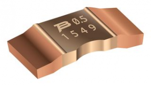
For the resistor we use an SMD Current Sense Resistor, 0.001 ohm, CSS2H-2512 Series, 2512 [6432 Metric], 5 W, ± 1%. This will give the required 1 mV/A response and can cope with a 30 A current.
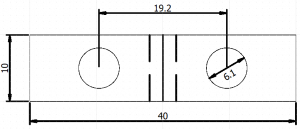
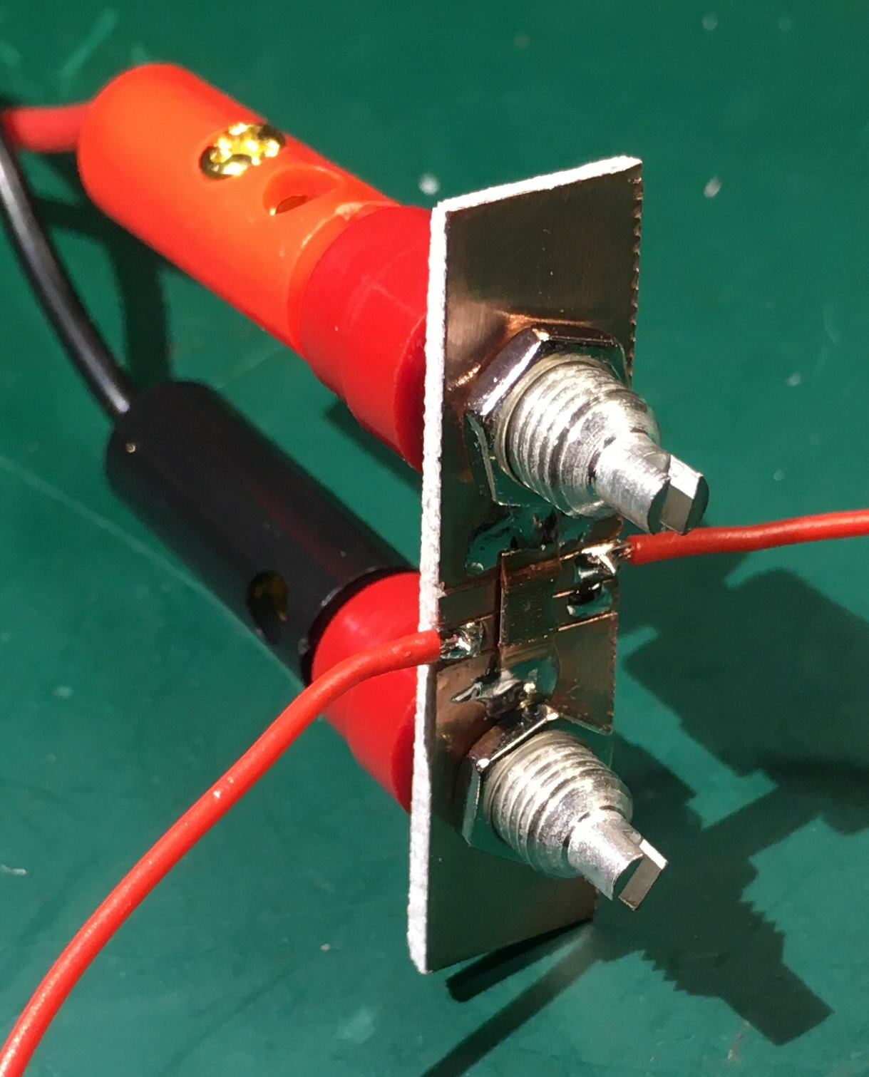
A small PCB was cut from a piece of copper clad FR4. The holes are 19.2 mm apart as this is a commonly used binding post separation. Care should be taken to route the sense connections as close to the ends of the resistor as possible.
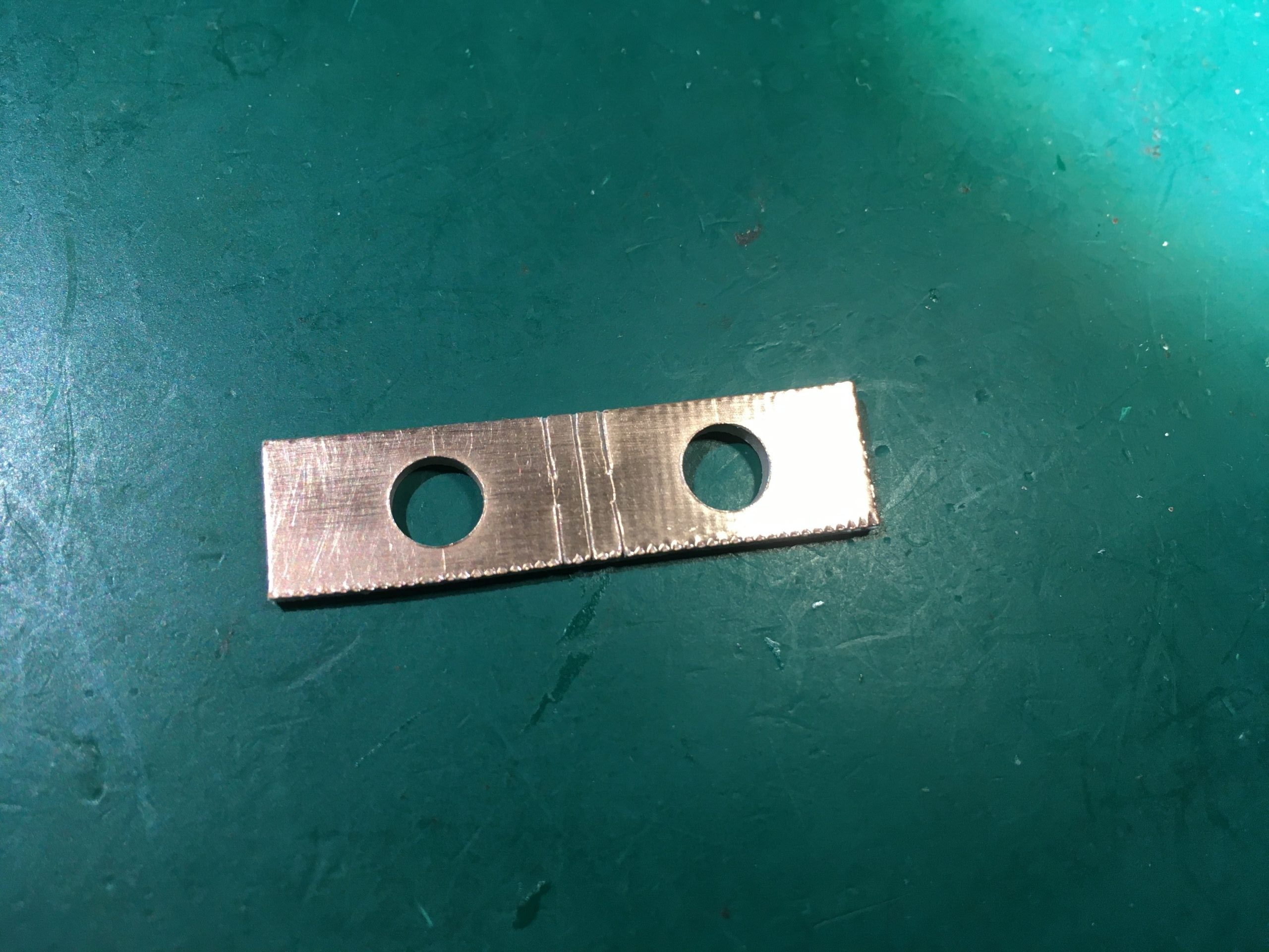
The resistor and sense leads were soldered on
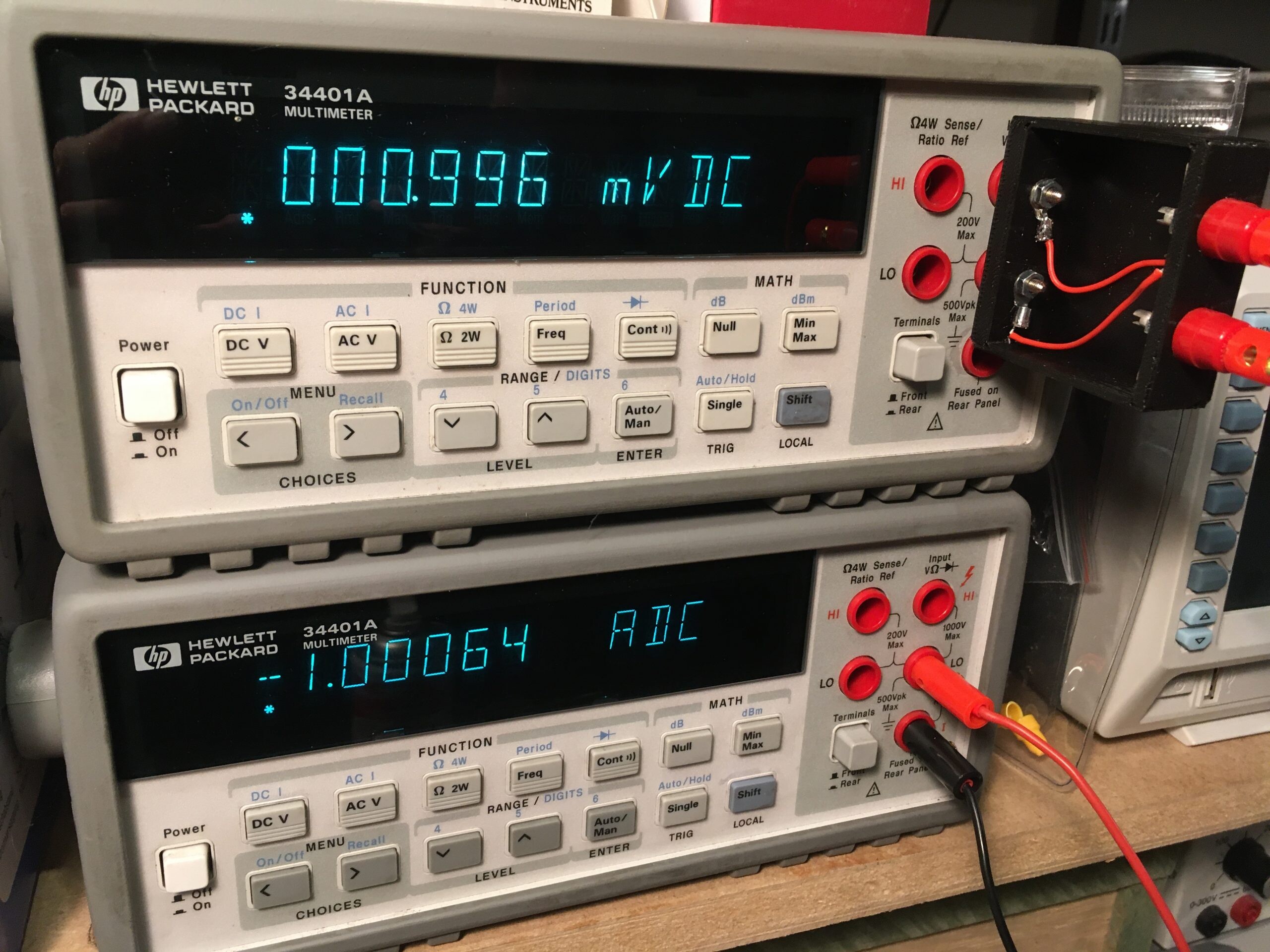
Mounted in a 3D printed box with banana sockets and plugs

Here is the shunt under test showing we are within 1% tolerance.
A couple of lessons learned:
- If any solder gets on the resistive part of the resistor it will reduce the resistance!
- The sense connections must be connected as close to the ends of the resistor as possible. A few extra micro-ohms will exceed the tolerance.