This project couples a variac with an isolation transformer.
Two design decisions to make:
1. Does the isolation transformer go before or after the variac? Here it was placed after the variac as the variac was rated to 4A and the transformer 5A. Any turn-on surge current will be less through the variac.
2. Is an earth connection passed through to the output socket? No, because it’s an isolation transformer 😉 For convenience the earth connection is made available separately on the front panel.
The schematic is straightforward:
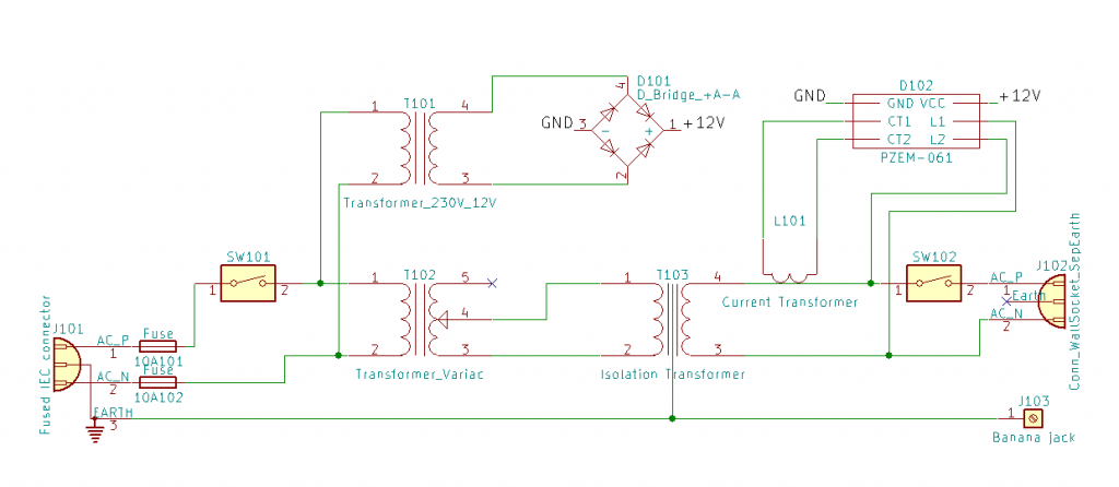
A PZEM-061 module is used to display output voltage, current and power. It is hacked (ref 1) to run off a separate 12V supply which is sourced from a small transformer to maintain isolation.
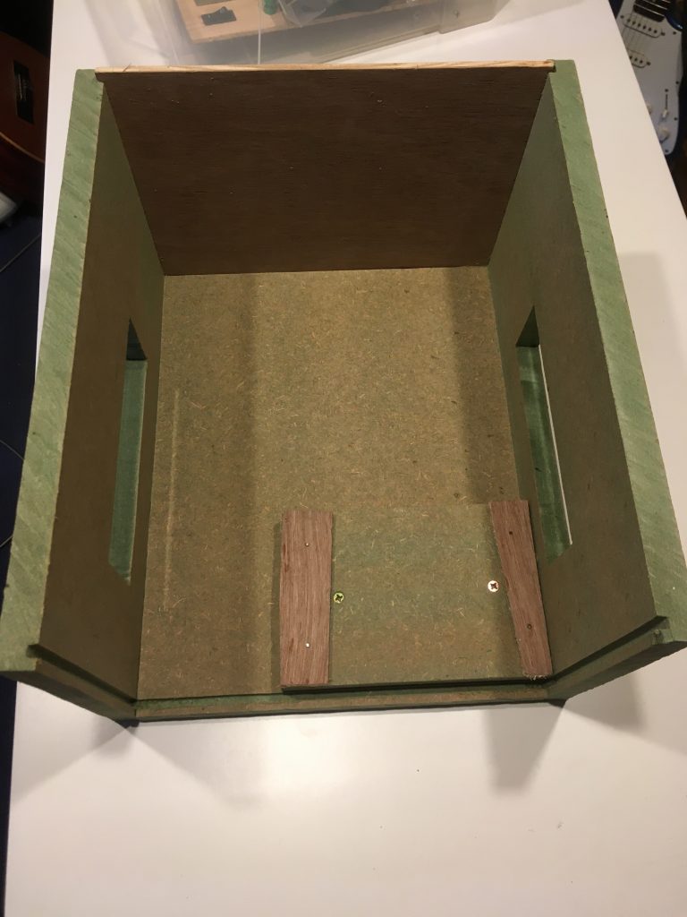
A box was constructed from MDF and plywood to contain the hardware.
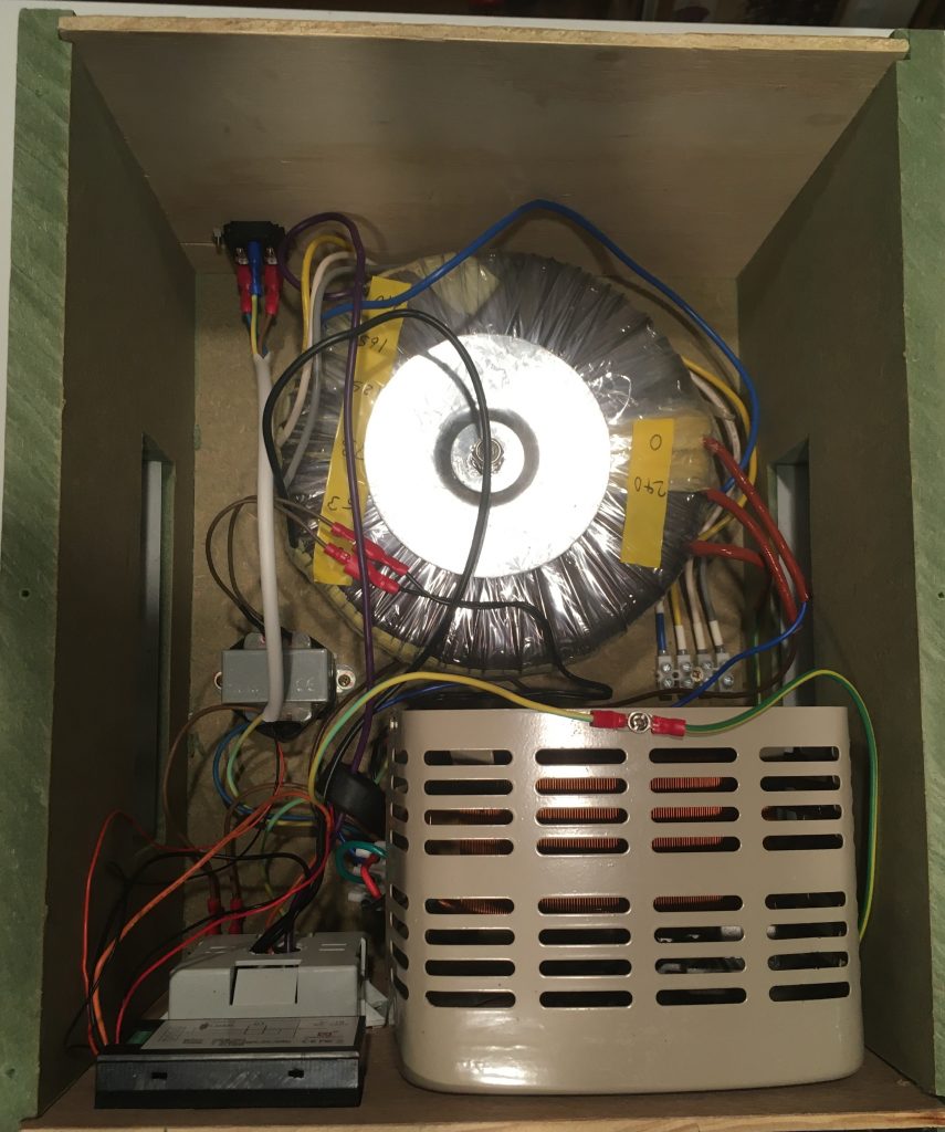
With two large transformers the unit weighs in at 25 kg.
The variac was positioned so it pokes through a hole in the front panel. Re-using its original scale gives a rough idea of the voltage and tidies up the hole. Even the rubber feet were reused.
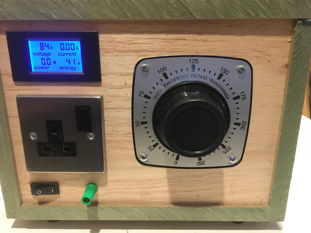
All finished and ready to use.
Refs: