Background and Motivation
I’ve long been interested in Bret Victor’s Dynamicland and RealTalk work, but I’ve also found it frustrating that the system is entirely closed-source. He has explained his reasoning for this, but it does limit the ability to experiment with the ideas first hand.
The only publicly available system in a similar space that I could find was the Folk Computer project. Although I have a fondness for Tcl and Linux, I ultimately decided to build a more conventional Windows-based C# implementation instead.
Source code is available at https://github.com/ynformatics/TabulaLuma
To be clear, I have no inside knowledge of Bret Victor’s system. This project is based solely on interpretations of his published papers, talks, and demos. These are excellent by the way, and I recommend browsing through them to get a better idea of the thinking behind this work.
TL;DR;
- Set up and calibrate the hardware as described below
- Use the FrameCodeGenerator program to print out frames with program ids 0 and 1
- Program 0 is a code editor, it will show a whisker pointing up. Move program 1 over the end of the whisker. You can now edit the code for program 1. Press Ctrl + S to save.
- print out frames with program ids 2, 3 and 4. They should display something when placed on the table. Bring them in range of the code editor to see the code. This is decompiled from the assembly bytecode. You can edit and save the modified code which will generate an overriding .txt script file.
Core Concept
The central idea is to give physical objects programmable behaviour.
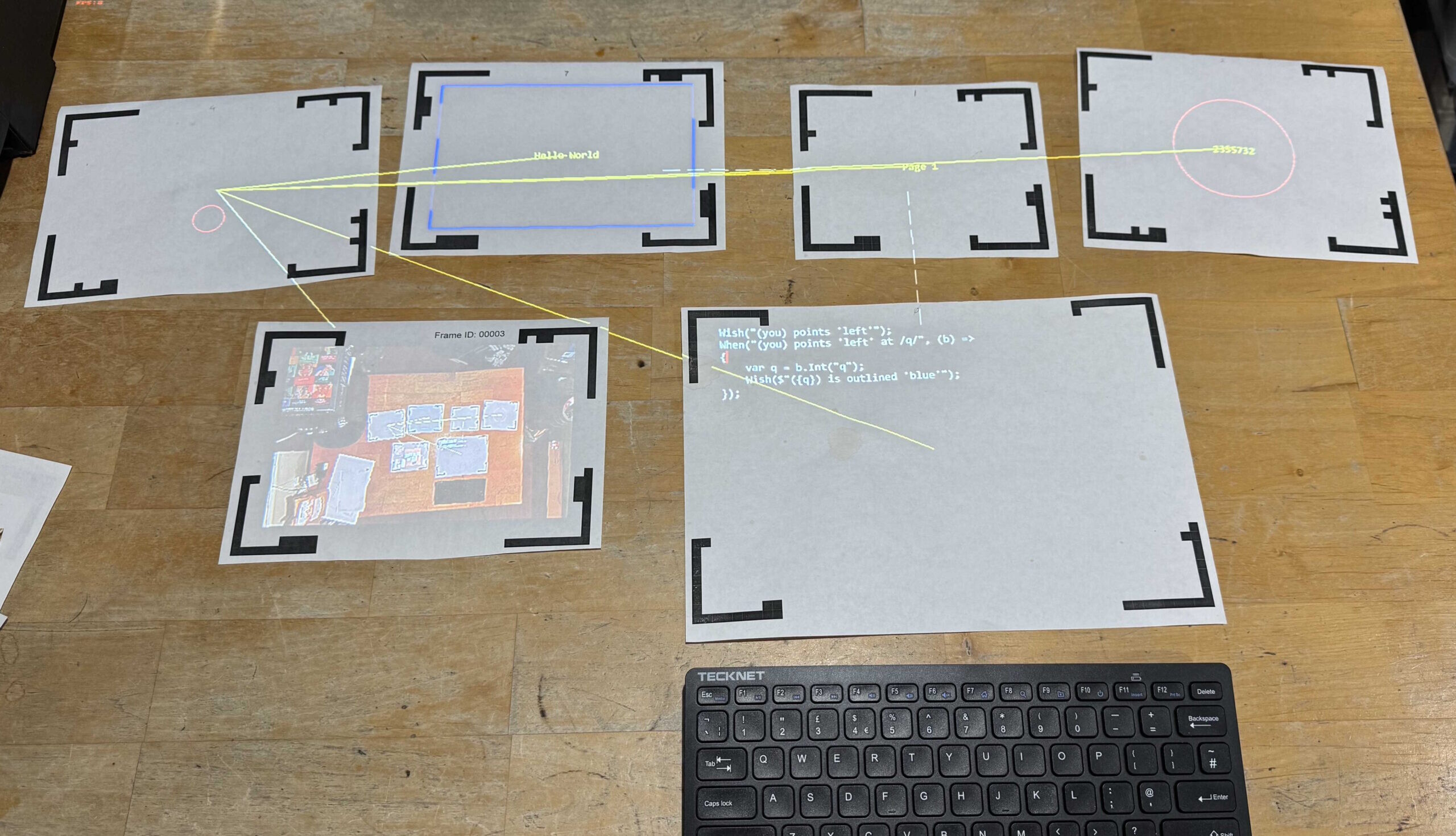
A canonical example is using sheets of paper tagged with fiducial markers. These markers allow the system to track each objects identity and position on a table. Programs can then be associated with individual pieces of paper, enabling text and graphics to be projected directly onto them using an overhead projector.
In effect, the physical paper becomes both an interface and a computational entity.
Reactive Programming Model
Programs in this system are written in a reactive style, built around three core concepts:
Claims
A Claim represents a statement of fact about the systems current state.
(page-1) has width 123.4
Claims describe what is.
Wishes
A Wish represents a desired state, something that should become true.
(page-1) is labelled "hello world!"
Wishes describe what should be.
Whens
A When defines the actions required to make a wish come true when certain conditions are met.
Conceptually:
When
/page-id/is labelled/label/, then draw the label on the corresponding page.
Whens form the bridge between declarative intent (wishes) and imperative behaviour (actions).
Implementing the Model in C#
Implementing this model in C#, a statically typed language, introduces some additional complexity. Dynamic languages such as Lua or Tcl are more naturally suited to this style, but it is still feasible in C# with careful design.
Claims and Wishes
Claims and wishes map cleanly to simple API calls:
Whens with Actions
A When statement associates a pattern with an action. The action receives a binding context that provides typed access to the matched variables.
In this example:
-
The pattern extracts the page identifier and label text
-
The action constructs a visual representation
-
A new wish asserts that the page should display that illumination
Note that any valid C# code can be used in the action block and the full .Net framework is available. Claims/Wishes/Whens can be nested as required.
Handling the Non-Matching Case
A When can also specify what should happen when it doesn’t match, using Otherwise:
This allows a rule to explicitly manage both its active and inactive states.
Attaching Options with with
A When may include an options list using the with keyword followed by name/value pairs. These must appear at the end of the statement:
The binding context exposes these values when the When is triggered by a Wish or Claim that supplies them.
Combining Conditions
A When can depend on multiple claims that must all be true (logical AND).
They can be expressed inline:
Or written in a more fluent, stepwise form using And:
Both forms express the same intent: the action only runs when all conditions are satisfied.
Memories, Remembering State Across Frames
In addition to Claim, the system provides a Remember statement. Like Claim, it injects a fact into the database, but it persists from the next frame onward:
Remember also supports optional temporal clauses:
This allows transient state to be modelled declaratively, without explicit timers or lifecycle management in user code.
Fiducial Markers
The system originally used AprilTags, which worked reliably but proved to be slower than desired. Inspired by the coloured dot frames used in RealTalk, I wanted a lightweight alternative that visually framed the active area while remaining fast to detect.
To keep printing simple and compatible with black-only printers I designed a new fiducial format called Corner Frames.
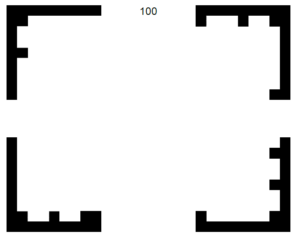
Each frame is composed of four independent corner markers:
-
Every corner contains:
-
Two outer solid strips for geometric detection
-
Two inner binary-coded strips for identification
-
-
Each corner provides 15 bit positions:
-
14 bits encode the identifier
-
1 bit is reserved for parity checking
-
This yields:
-
2^14 possible codes per corner
-
A frame consists of four sequential corner codes
-
Because of this sequencing, only three corners are required to uniquely identify and locate a frame
-
The system supports 2^12 – 1 = 4095 distinct frame IDs
This structure introduces redundancy while allowing robust recovery from partial occlusion.
Corner Detection Pipeline
Corner detection proceeds through a simple, fast image-processing pipeline:
-
Apply Otsu thresholding to binarize the image
-
Extract contours whose area lies within a configured range
-
Fit bounding boxes to each contour and reject those that are not:
-
Approximately square
-
Within the expected size range
-
-
Locate the coded strip within each candidate corner and decode it
-
Reject any corner whose parity check fails
At the end of this stage, the system has a set of validated, decoded corners.
Frame Reconstruction
Once individual corners are detected, the system searches for groups of sequential codes starting at a multiple of four:
-
If four sequential corners are found, a complete frame is identified
-
If three sequential corners are found, the system infers the position of the missing corner and reconstructs the frame
This allows frames to be recognized even when partially obscured or outside the cameras view.
When a frame is successfully assembled, its corner coordinates are passed back to the main program, where they become part of the world model and can participate in claims, wishes, and reactive rules.
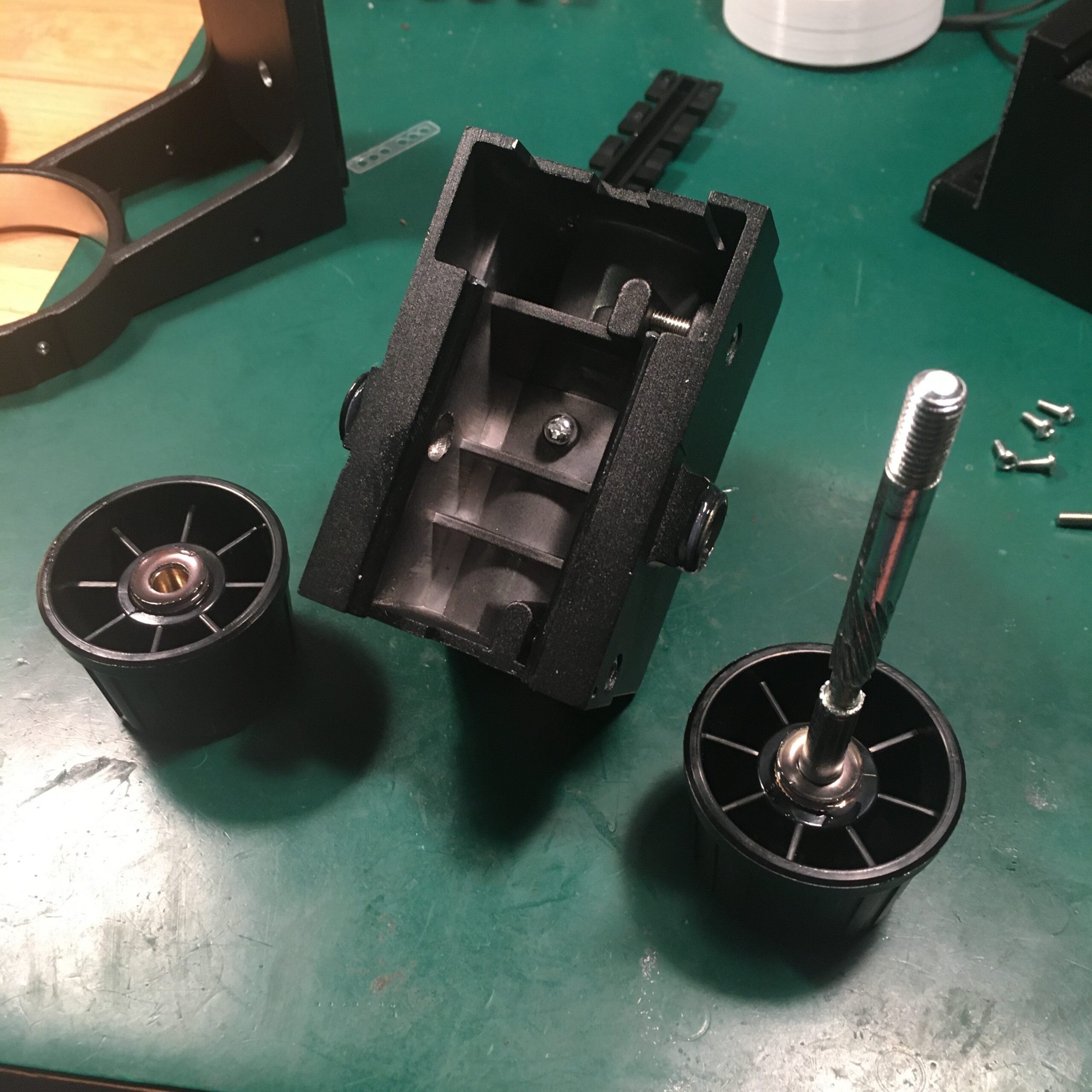
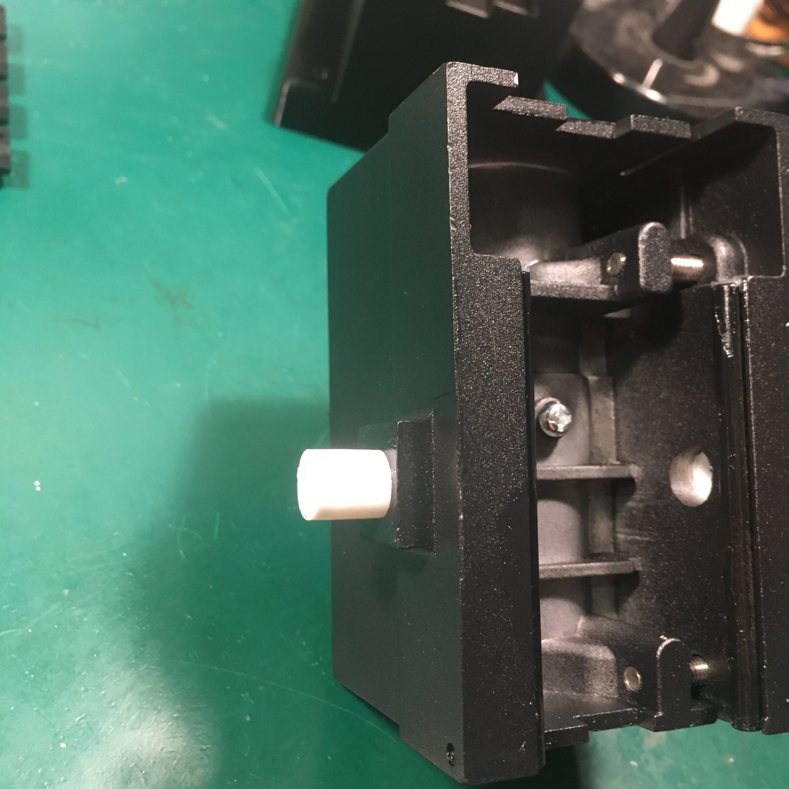
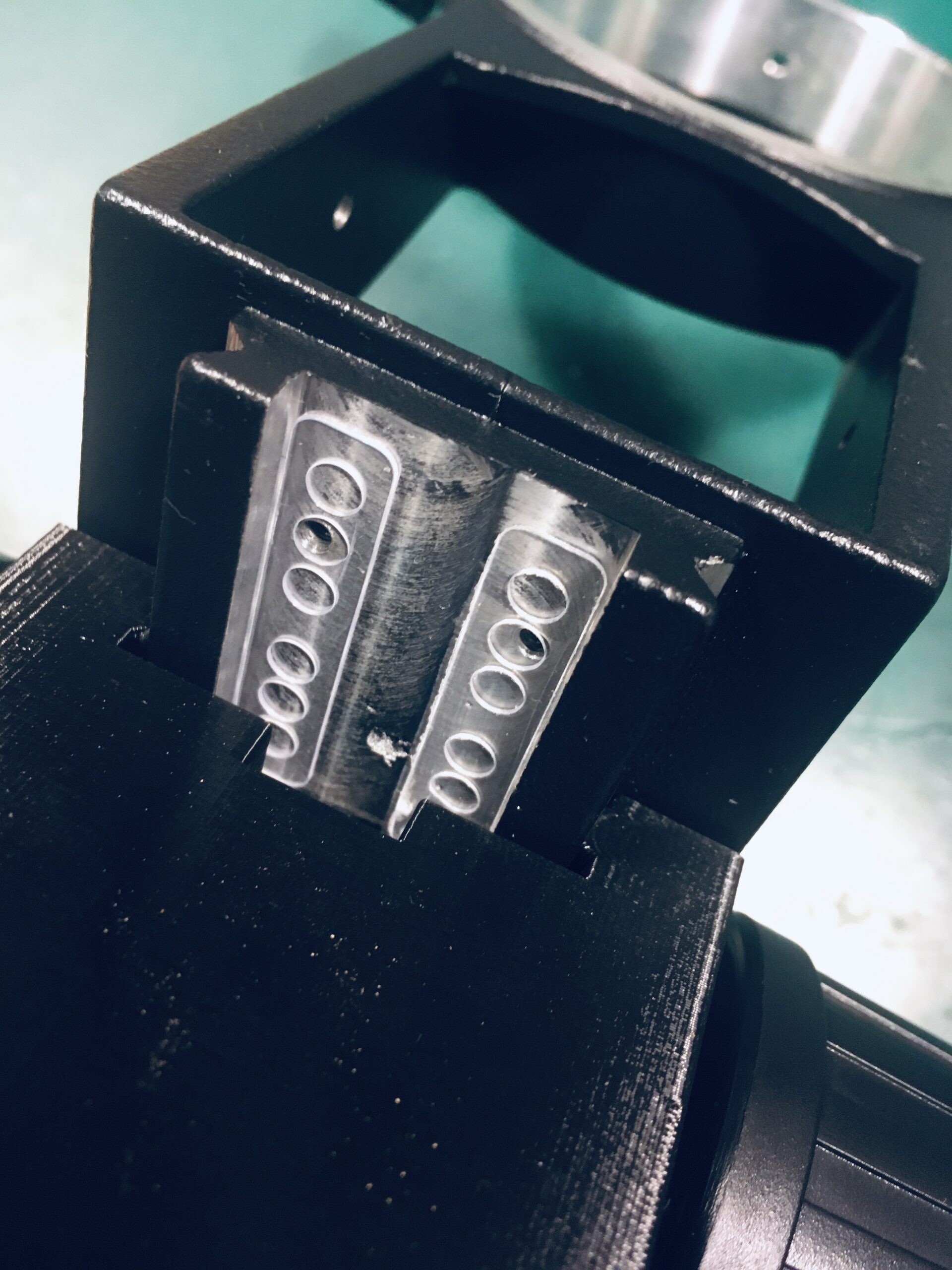
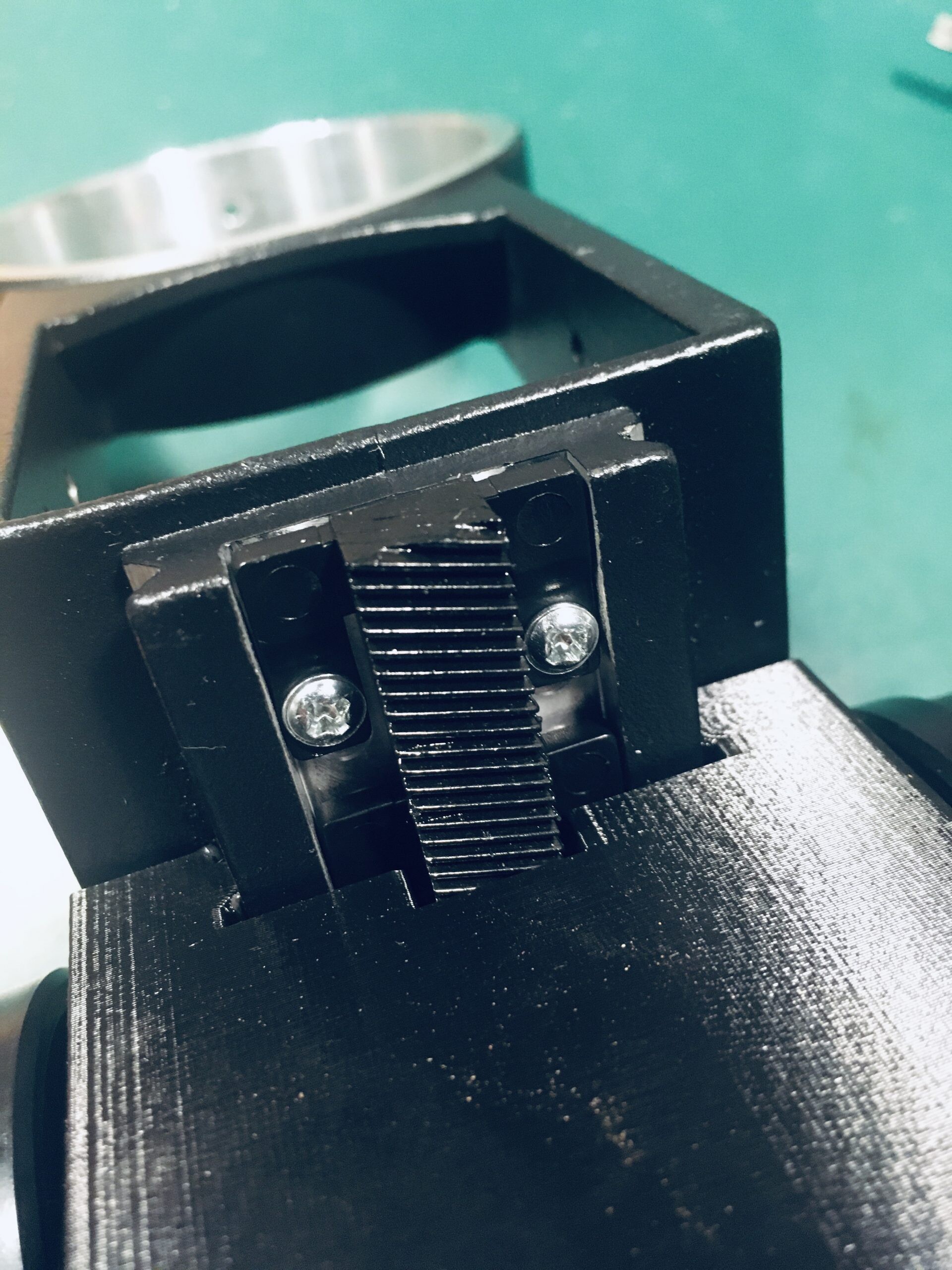
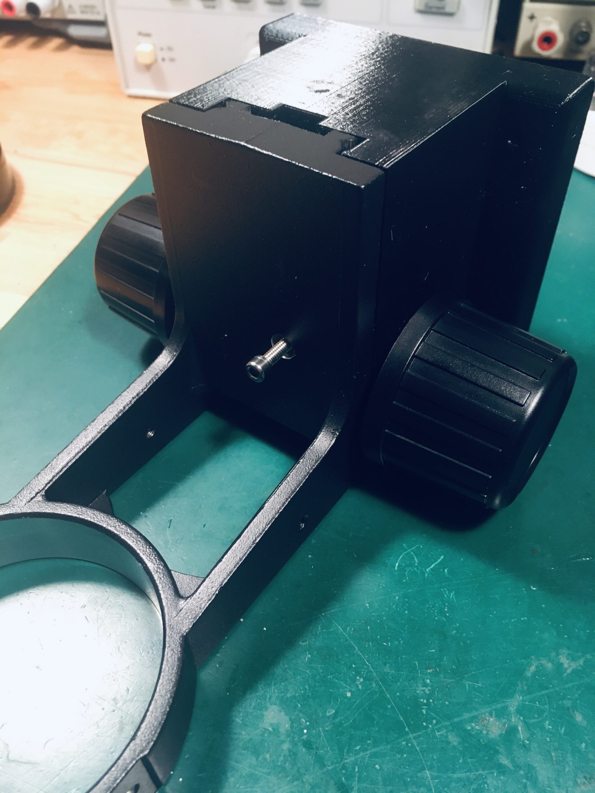
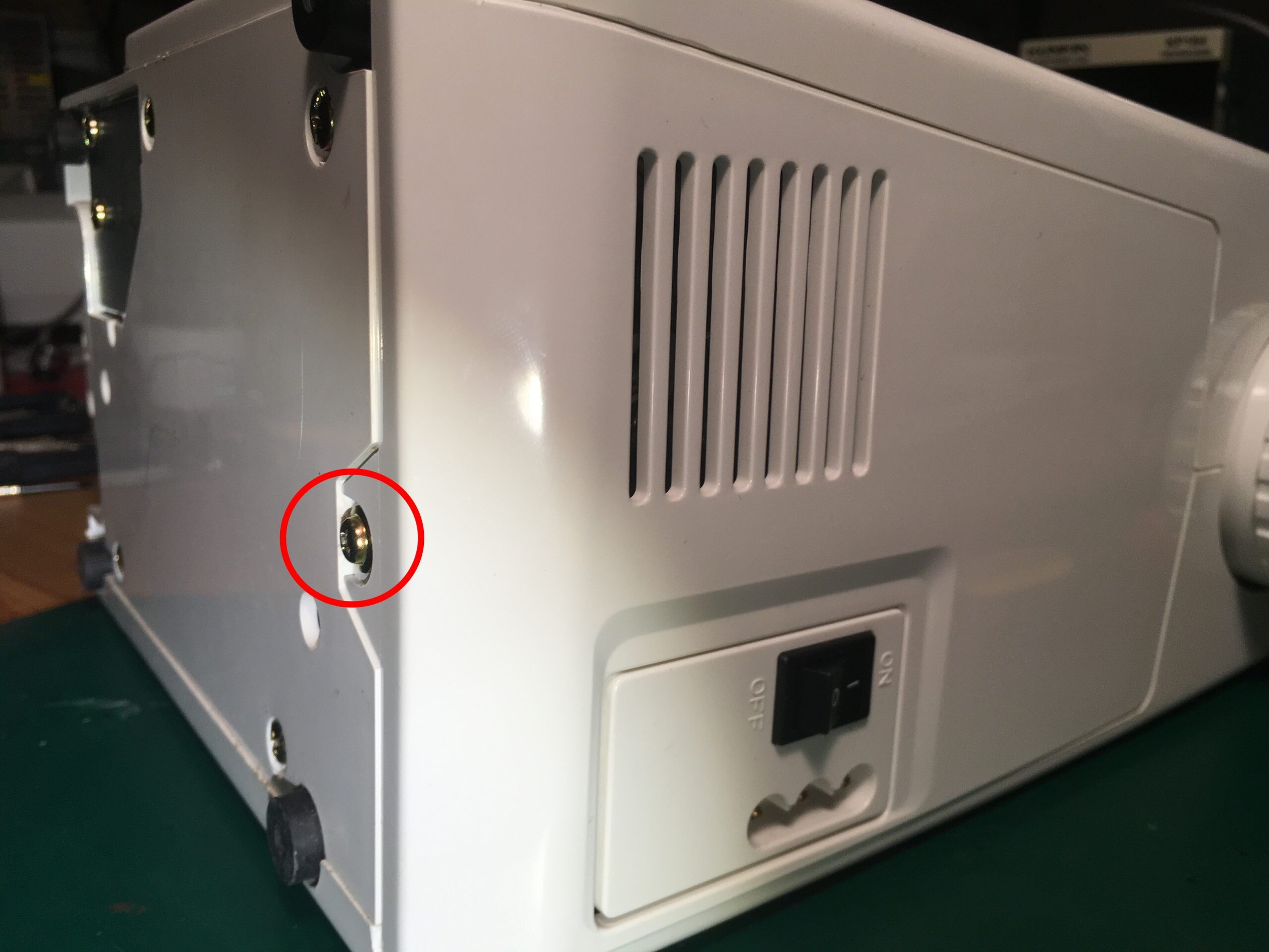
Hardware Setup
Begin by mounting both a projector and a webcam so that they have a clear, unobstructed view of the table surface.
Both devices should operate at a minimum resolution of 1920 x 1080. The software is developed and tested at this resolution; higher resolutions should also work, but may require minor adjustments within the code.
The reference setup uses:
-
Logitech C920 webcam
-
WiMiUS P62 projector
Other hardware combinations are likely to work, provided they meet the resolution and mounting requirements.
Camera Calibration
Turn the projector off for this procedure.
-
-
Use the Corner Frame Generator to print a set of Corner Frames and lay them out on the table surface.
-
Launch the Tabula Luma application.
-
Press Ctrl + K to start the camera calibration mode.
-
Adjust the camera:
-
Use Shift + F / f to increase or decrease focus
-
Use Shift + E / e to increase or decrease exposure
(Uppercase increases the value; lowercase decreases it.)
-
-
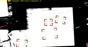
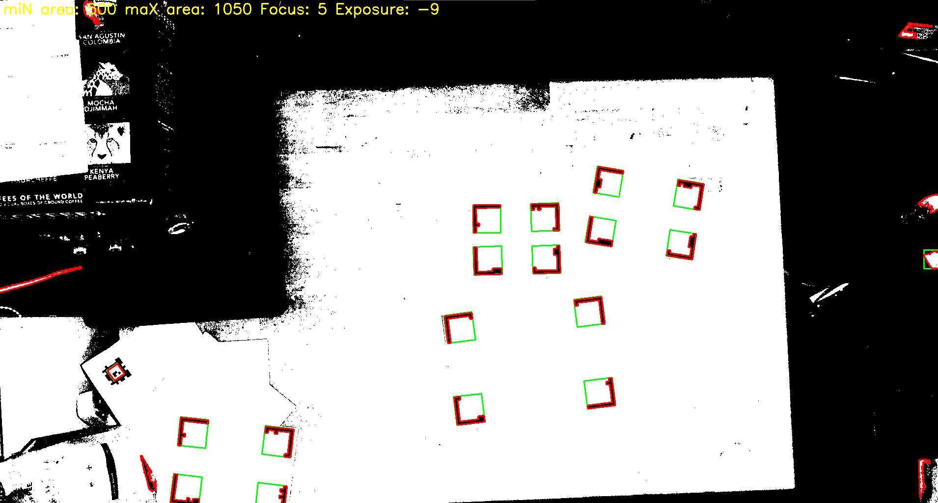
Tune the minimum and maximum area detection parameters until the Corner Frames are outlined in red. It is OK to have a few spurious detections.
- Use Shift + X / x to increase or decrease max area
- Use Shift + N / n to increase or decrease min area
-
When a Corner Frame is successfully detected, a green square will appear around it.
-
Adjust lighting and calibration parameters to achieve the most stable and accurate detection possible.
-
Once detection is reliable, press Ctrl + S to save the calibration values.
-
Press Escape to exit the calibration program.
-
At this point, the camera is configured to reliably recognize the fiducial markers under your current lighting and table conditions.
Camera /Projector Calibration
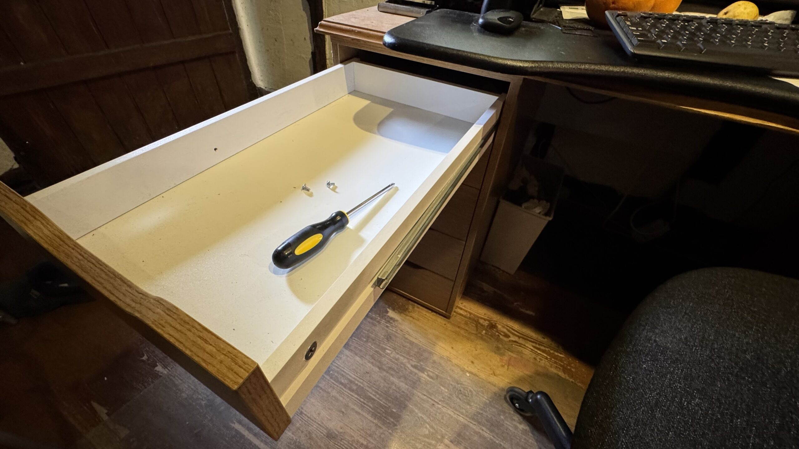
Accurate calibration is essential for reliable table-surface tracking. Before starting, clear any objects from the tabletop to ensure the camera has an unobstructed view.
1. Display the Calibration Pattern
Make sure the projector is turned on and adjust it for best focus.
Press Ctrl + L to display the on-screen calibration pattern. The interface should show four blue squares, with a central blue dot.
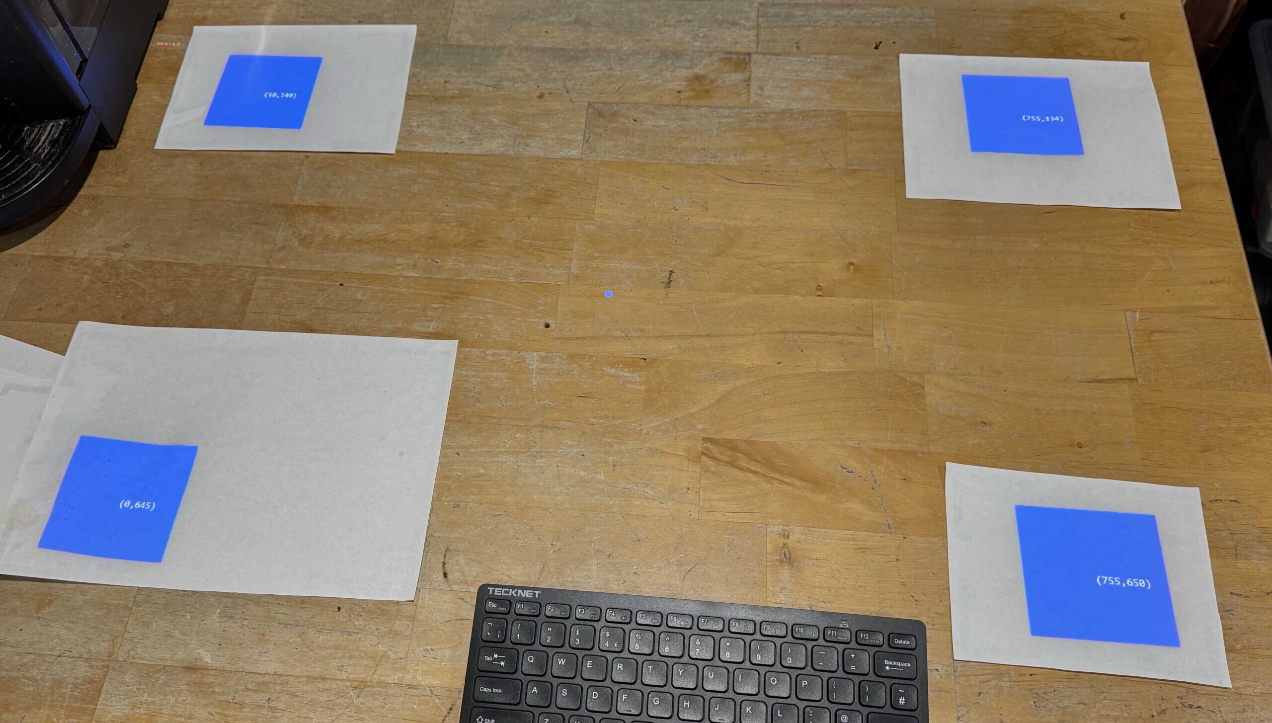
Use the arrow keys to adjust the scale of the pattern. For optimal detection, expand the pattern so that the four squares are positioned as far apart as the display allows.
A small blue dot will be seen in the centre of the pattern when it has been successfully recognized. If the dot does not appear, try placing sheets of plain white paper beneath the squares. Since the detection algorithm relies on recognizing a specific blue hue, variations in lighting or table texture can interfere with detection.
Once the pattern is correctly recognized, press Ctrl + S to save the calibration.
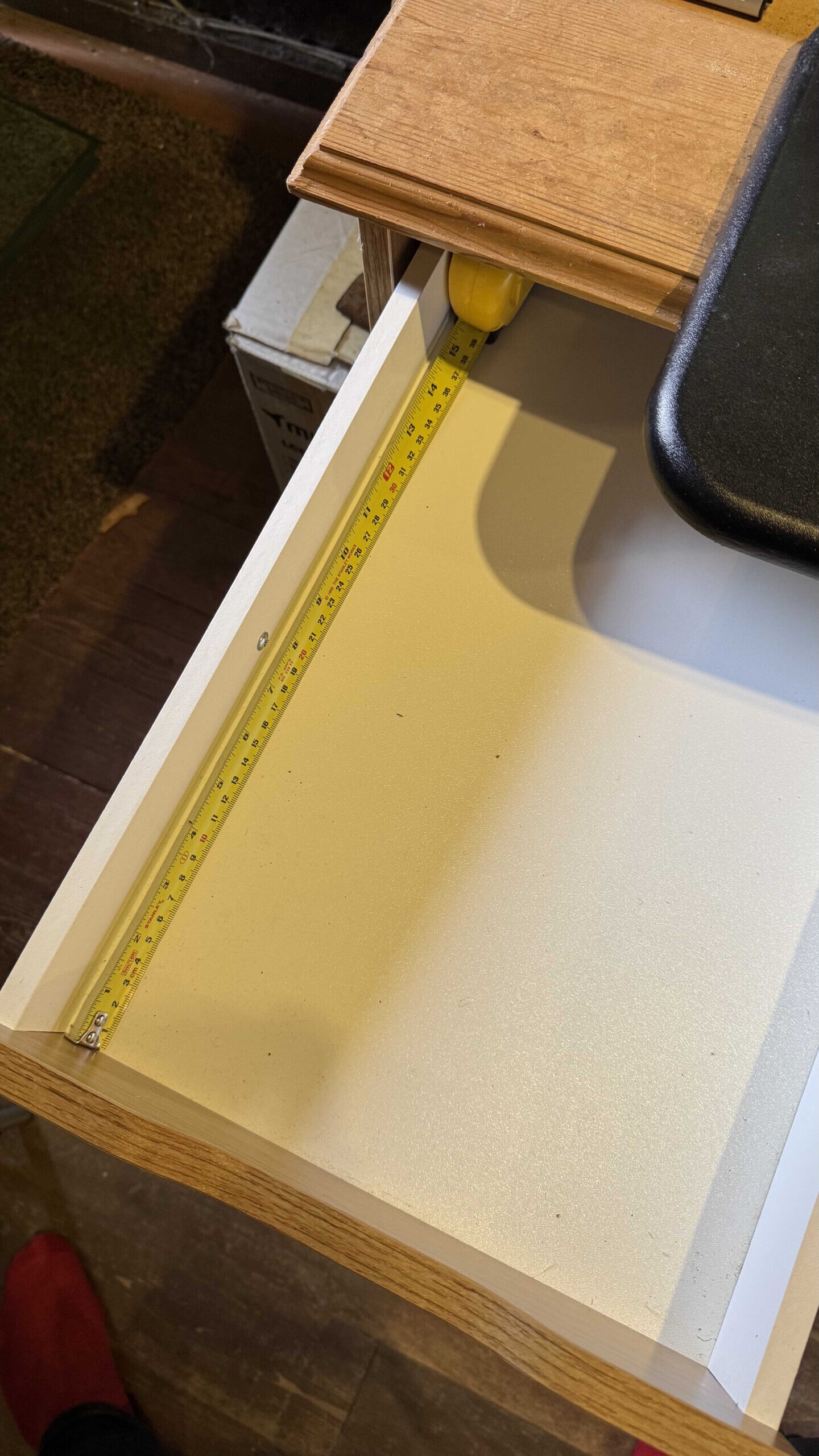
2. Define Real-World Coordinates
After saving, the system needs the actual physical coordinates of the patterns outer corner points.
-
-
-
Choose a coordinate system, for example:
-
Origin at the top-left corner
-
X increases to the right
-
Y increases downward
-
-
Measure the real-world coordinates (e.g., in millimetres) of each outer corner of the pattern.
-
Open the configuration file located at:
%LOCALAPPDATA%\TabulaLuma\config.txt -
Locate the
"WorldPoints"section. This array defines the world-space coordinates of the four corner points, starting at the top-left and moving around clockwise. -
Replace the existing values with your measured coordinates and save the file.
-
-
Principles of Operation
At start up, the system loads its configuration from:
If no configuration file exists, a default one is created automatically. The camera subsystem is then initialized using these settings.
Program Discovery and Loading
The next phase loads all available programs. A program is any class that derives from ProgramBase and implements IProgram.
All assemblies in:
are scanned using reflection. Any types implementing IProgram are instantiated and loaded into memory. This includes both the main TabulaLuma.dll and any external assemblies placed in the directory, enabling a plugin-style architecture.
In addition to compiled assemblies, the system also supports scripted programs. Any .txt files in the same shared directory are treated as C# source:
-
For each file, a new class derived from
FunctionBaseis generated -
The files contents become the body of the virtual
RunImpl()method -
The filename (minus extension) becomes the
ProgramId
If a duplicate ProgramId is encountered, the later definition overrides the earlier one. As scripted programs are loaded after built-in ones they will take priority in the event of a duplicate.
Frame Processing Pipeline
A background task is started to continuously capture images from the camera. Each frame is placed into a BlockingCollection, decoupling acquisition from processing.
The main thread then enters a loop, waiting for the next camera frame. For each frame:
-
-
Clear the fact database
-
Extract any CornerFrames from the image
-
Run all resident programs asynchronously
-
Run any programs associated with detected corner frames, passing the corner frame coordinates as arguments
-
Inject system-wide Claims (for example, the current clock time)
-
Wait for all program tasks to complete
-
Draw any generated Illuminations into the display buffer
-
Render the buffer to the projector
-
Each iteration represents a complete world update: perception, inference, program execution, and projection.