STL file downloaded from: https://www.thingiverse.com/thing:4853500
Printed on a Prusa i3 MK2 in PLA, 0.2 mm resolution, 25% honeycomb infill.
Some instructions and pictures of the conversion.

.
All done!
STL file downloaded from: https://www.thingiverse.com/thing:4853500
Printed on a Prusa i3 MK2 in PLA, 0.2 mm resolution, 25% honeycomb infill.
Some instructions and pictures of the conversion.
All done!
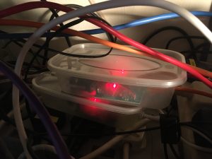
I needed to connect some more test equipment to my LAN. Currently this is done with individual Serial-to-Ethernet adapters in takeaway curry containers but this was getting ungainly and wasteful of internet ports.
Commercial 8-port RS232 to ethernet devices are available, but expensive, so time to DIY! I had a teensy 4.1 on hand and this looked like a good contender with in-built ethernet PHY, eight hardware serial ports and an Arduino compatible software stack (Teensyduino). It just needs an external Ethernet jack with magnetics (from PJRC) and eight RS232 DB9 connectors with MAX3232 level shifters (£1 each from from china).
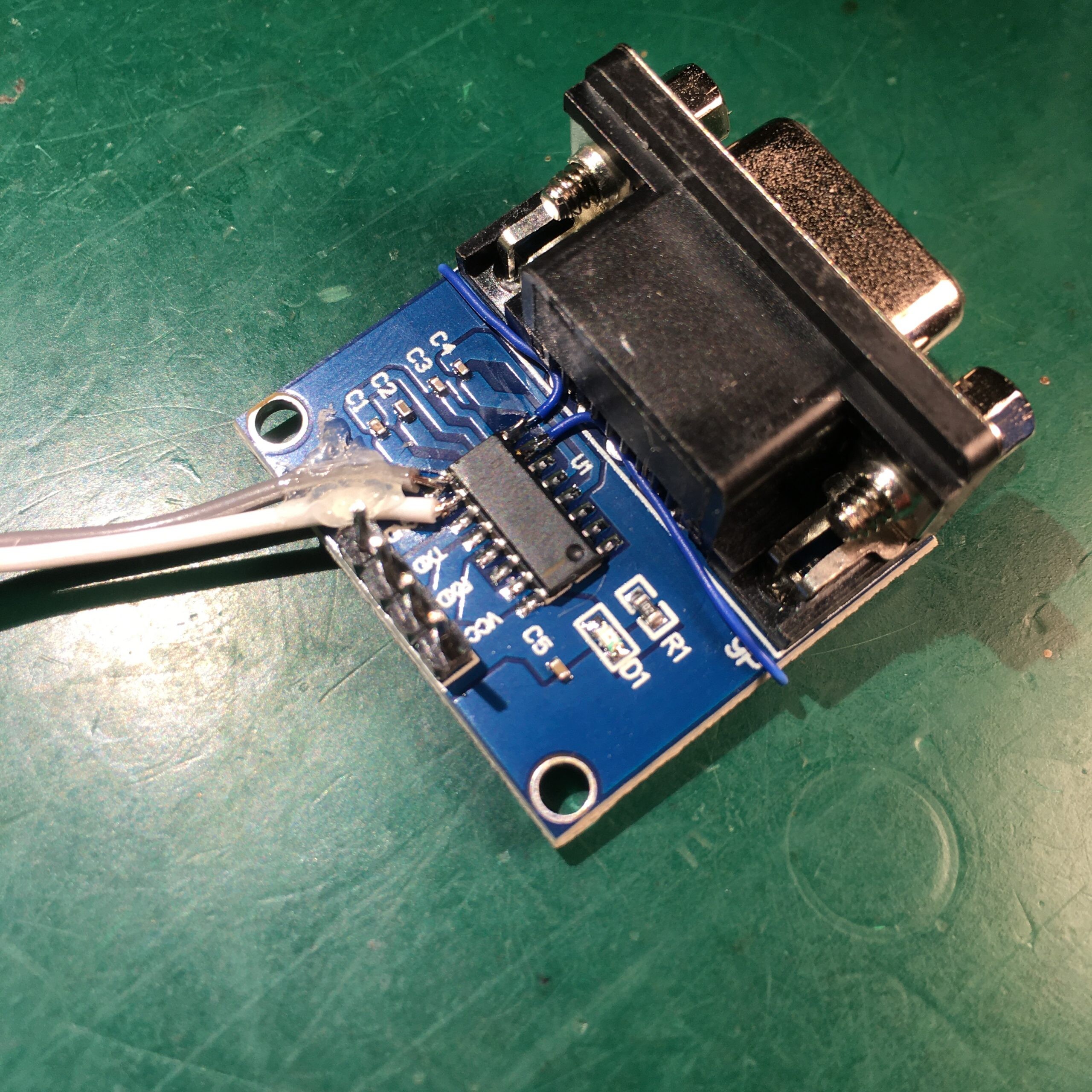
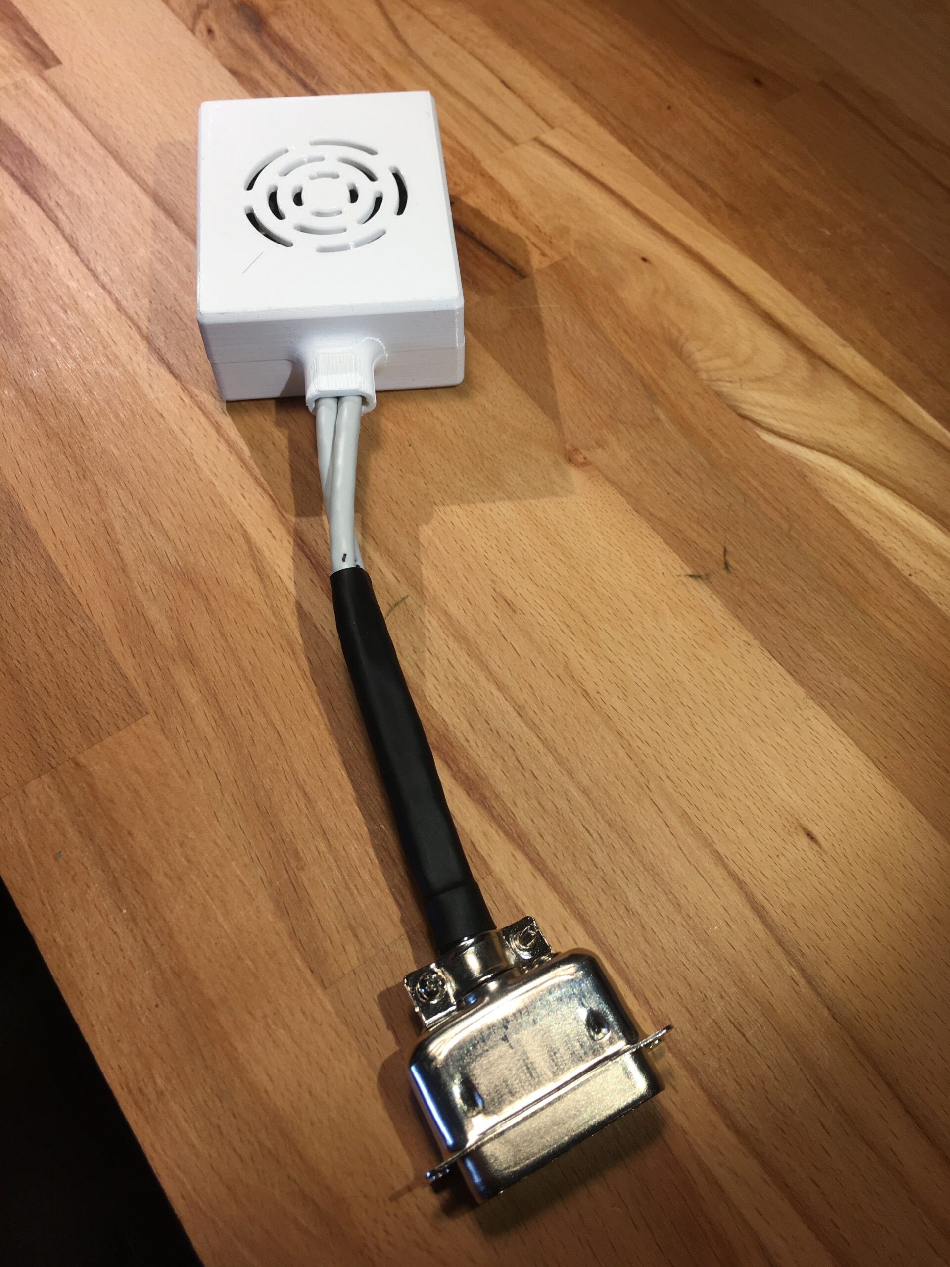
The level shifters typically come with just TX and RX pins connected. They can be easily hacked to add CTS/RTS support. Just connect CTS (pin 7 on the DB9) to pin 8 of the MAX3232 and RTS (DB9 pin 8) to MAX3232 pin 7. Logic level CTS/RTS are then available on IC pins 9/10 respectively. Here are some pics of the mods I made:

For software we need 8 TCP listeners each listening to a different port at the same IP address. I had trouble getting the NativeEthernet library to reliably support 8 connections but the QNEthernet library worked fine.
The algorithm just loops around each TCP port, and if there are any incoming bytes available reads them and forwards them to the corresponding serial port. And vice versa.
There is also an embedded webserver that allows configuration of the networking and serial port parameters.
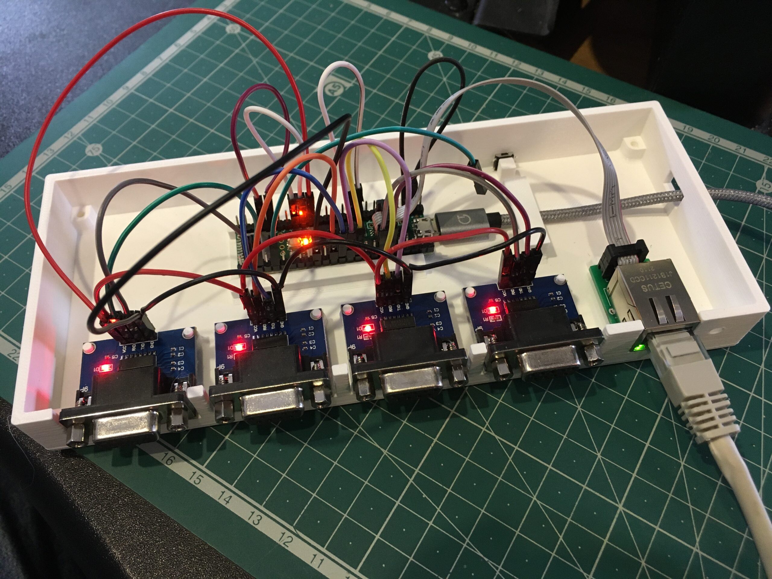
Here is the teensy being tested with each serial port looped back to itself. Grounding the green wire reboots the board in webserver mode where device settings can be configured.

Next a 3D printed case was designed in Fusion 360
Here is the bottom section with 4 serial ports installed. A few dabs of hot glue can be used if needed to keep things in place. If you only need 4 ports then the top can be fixed at this point.
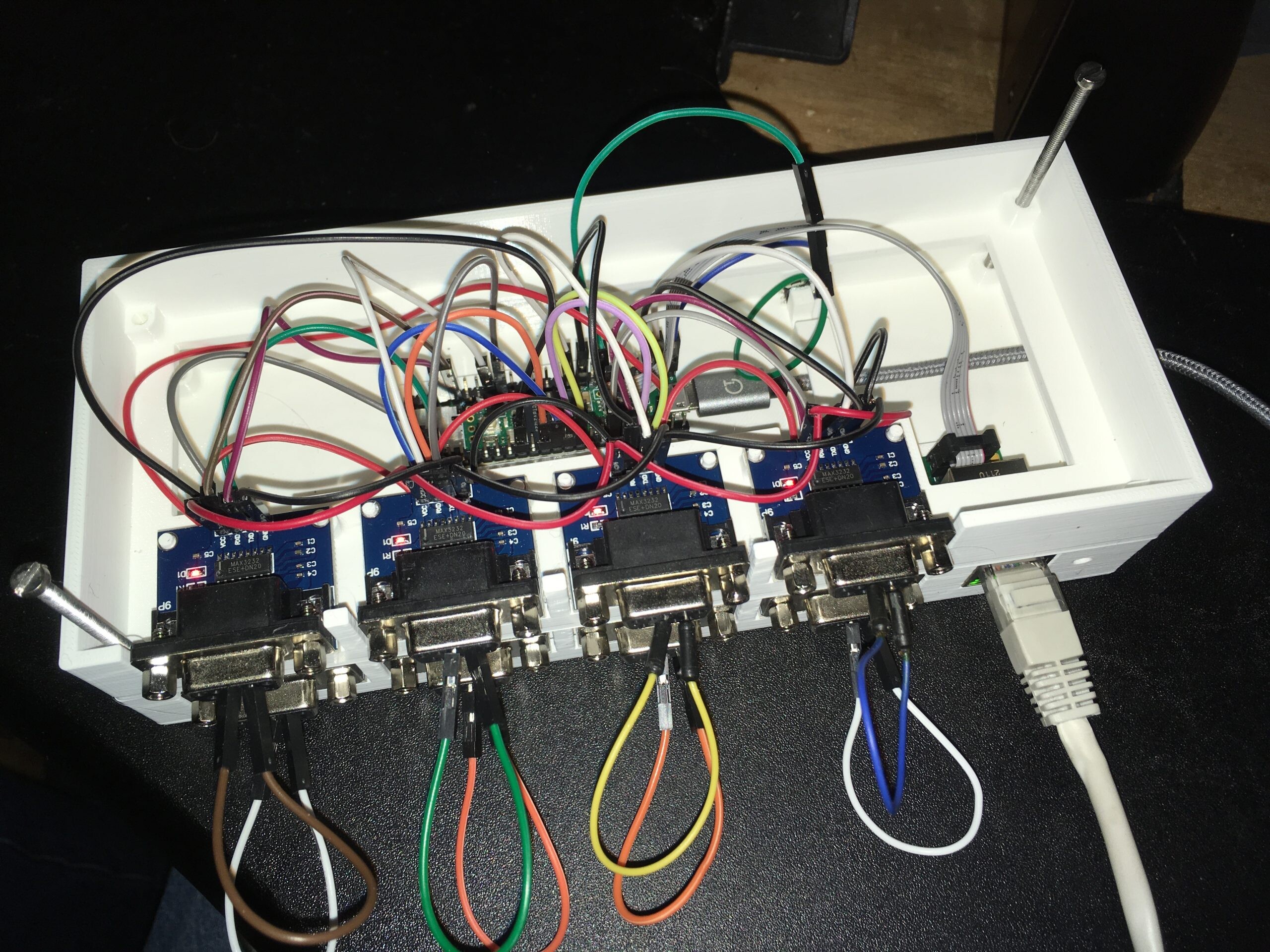
Here showing the middle 3D printed layer in place with the top 4 serial ports. A small tactile switch to enable config mode has been glued in. At this point all RX/TX pairs are looped back for testing.
And finally the top is added and all three layers sandwiched with 53mm M3 machine screws.
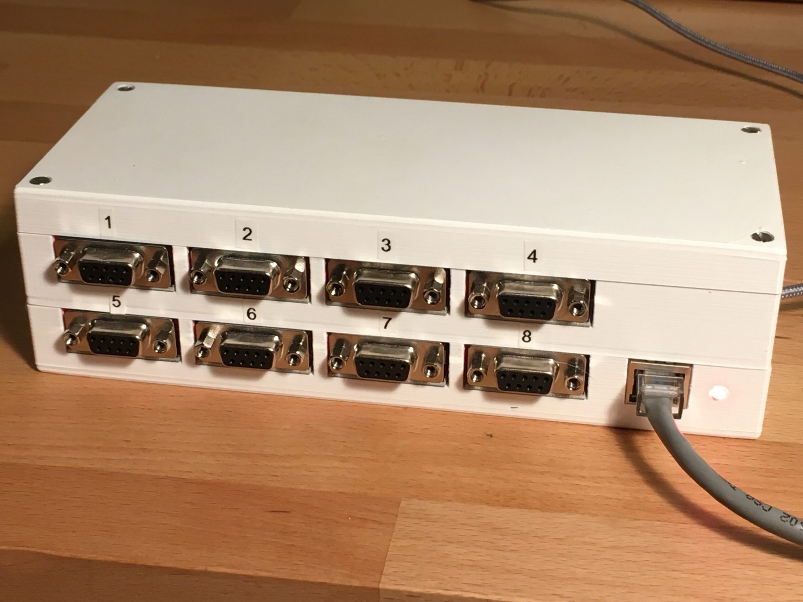
Now off to rip out the takeaway containers and tidy up the wiring!
Teensy software available here
Fusion 360 CAD files here
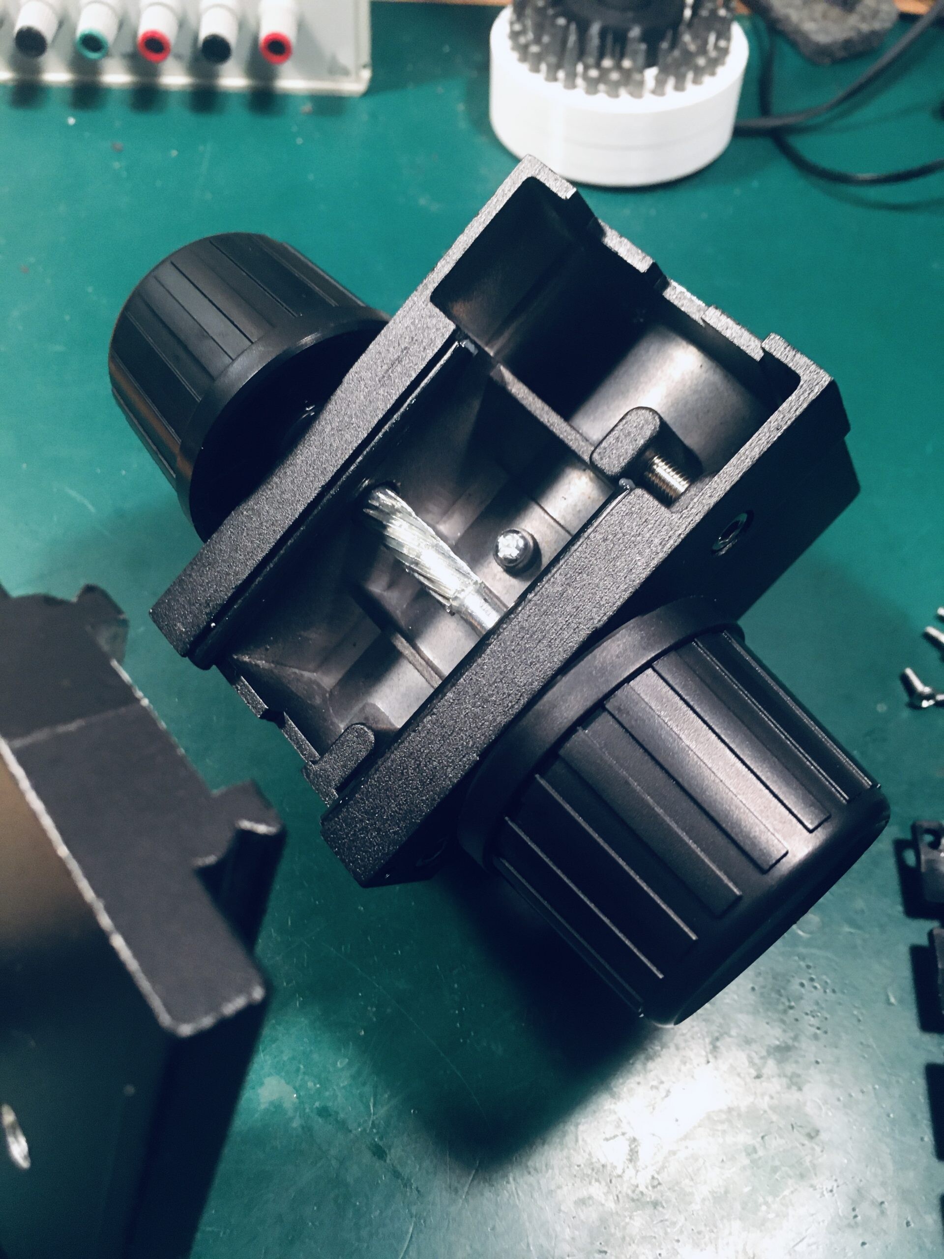
A New Home Model 1585 was stuck in reverse. Can we fix it?
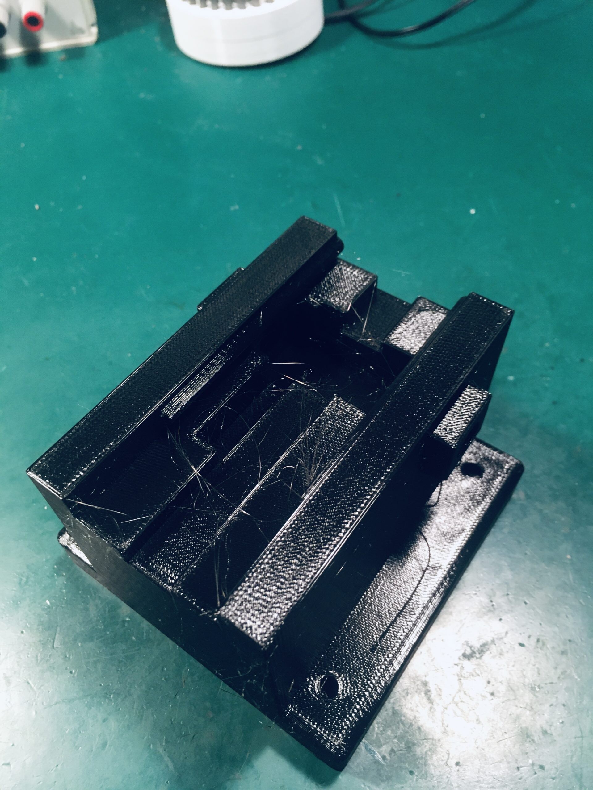
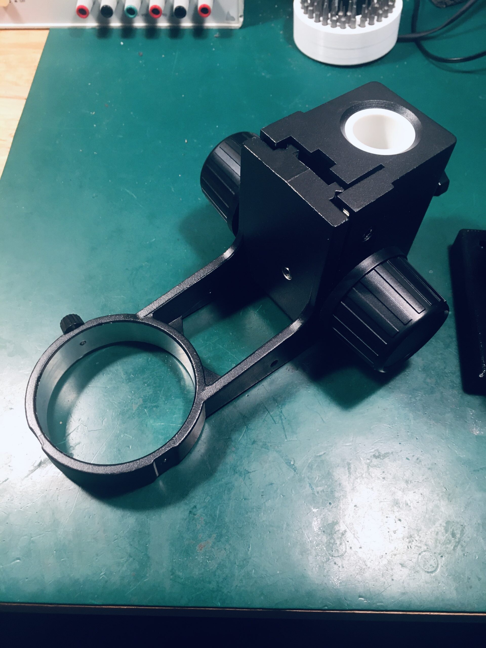
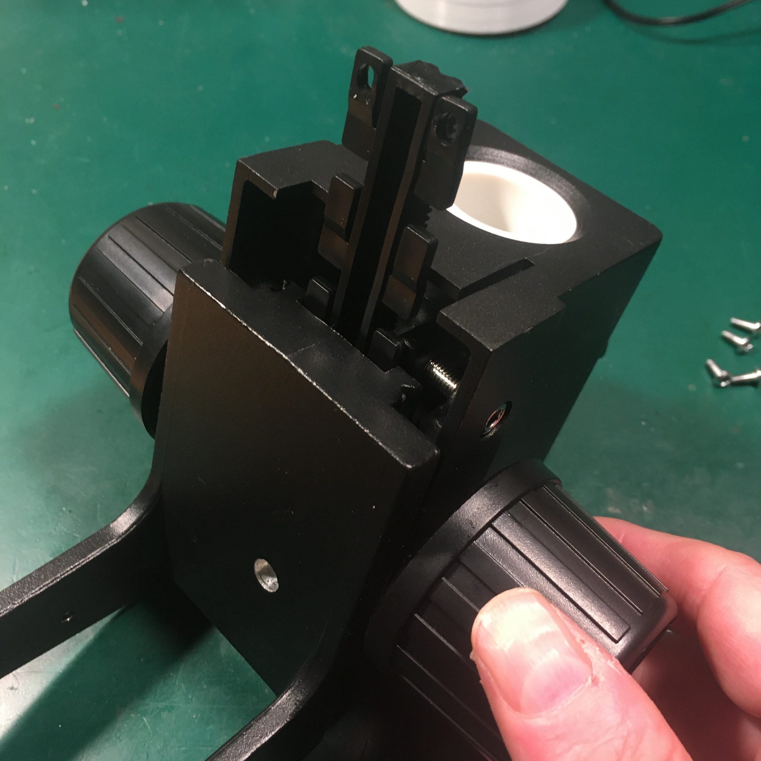
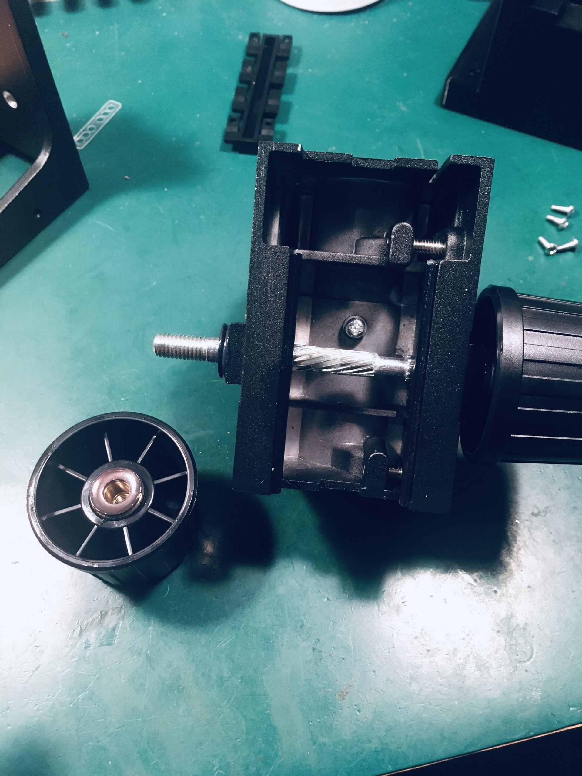
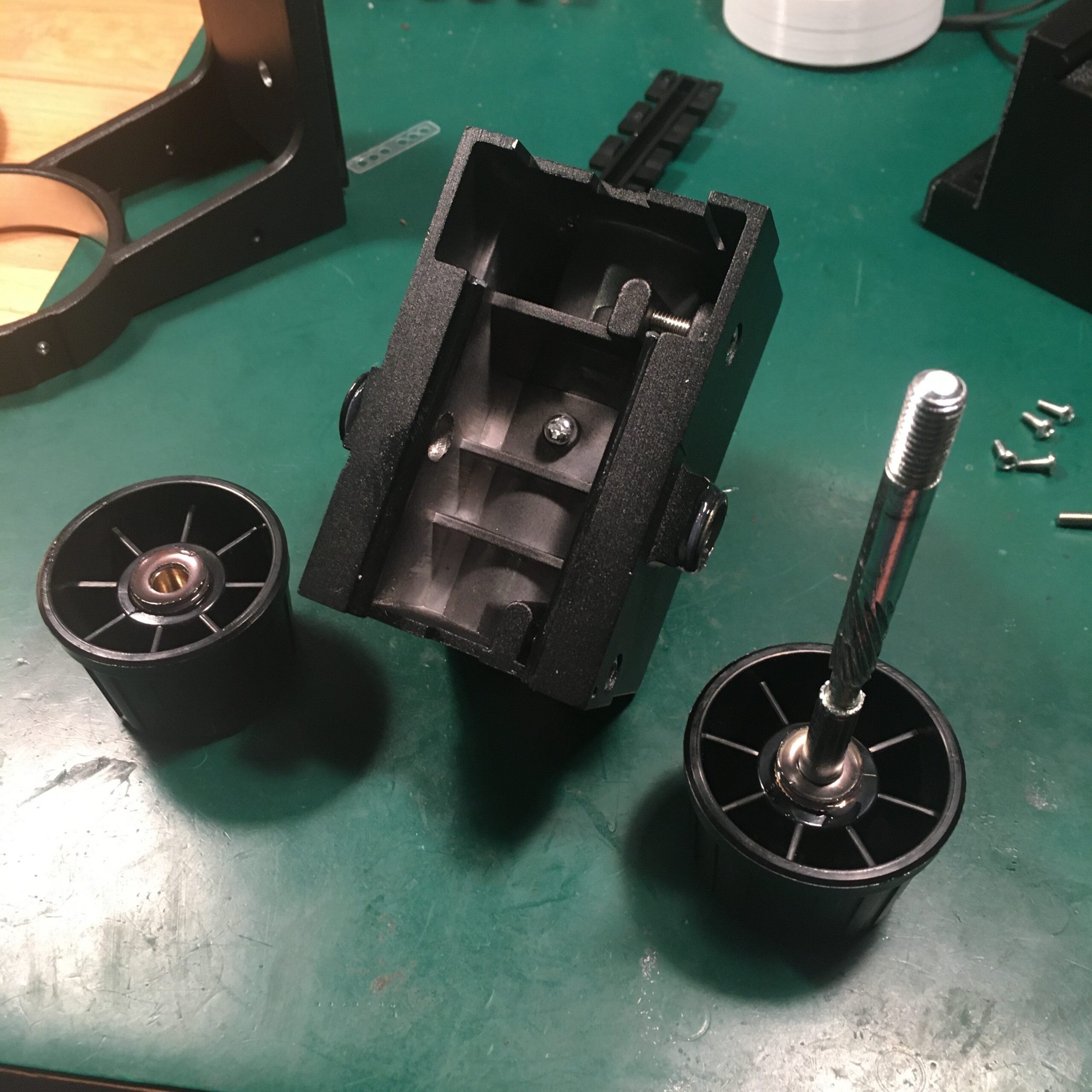
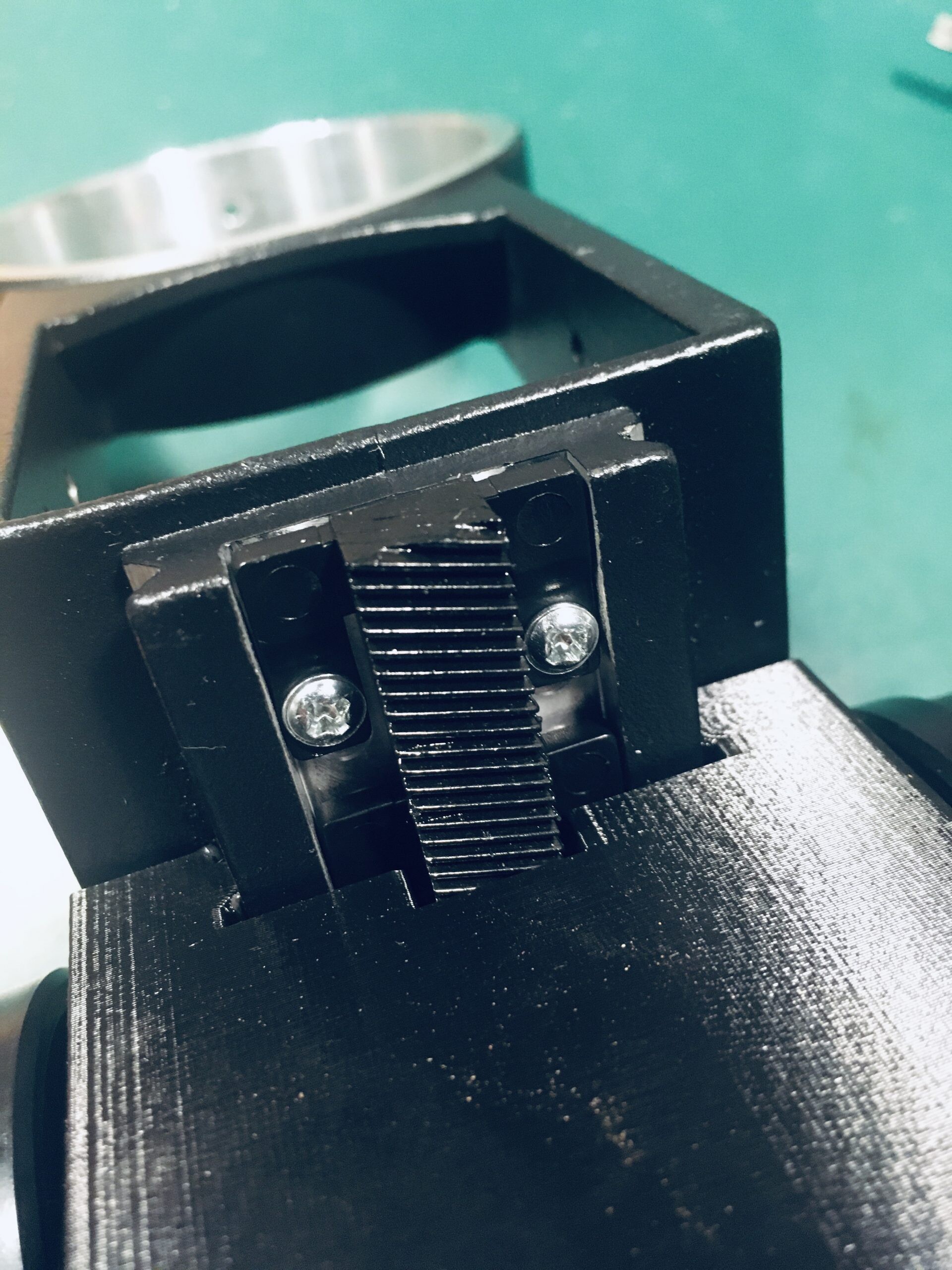
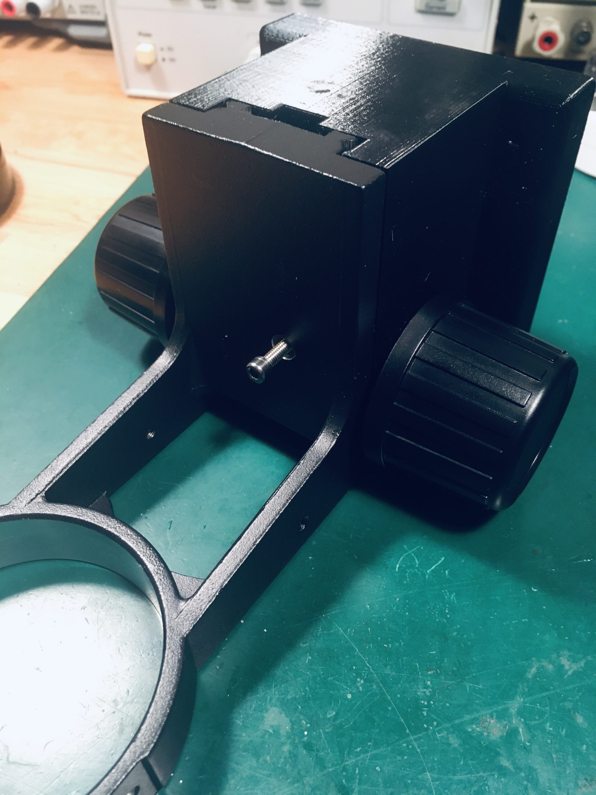
First step is to remove the front cover.

Pull off the knobs, remembering their position (there are some index holes if you forget)
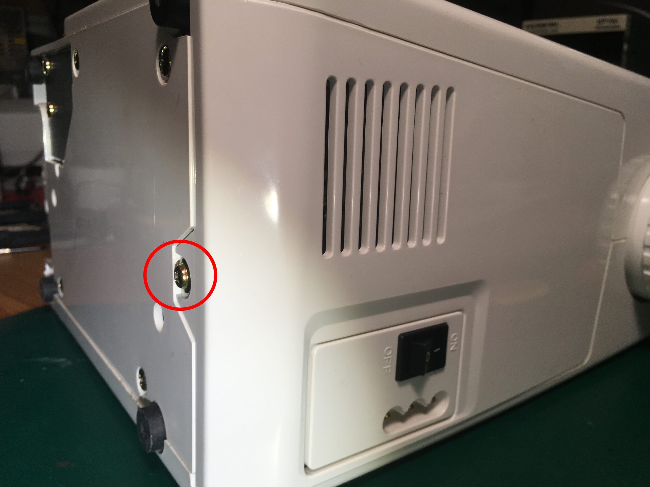
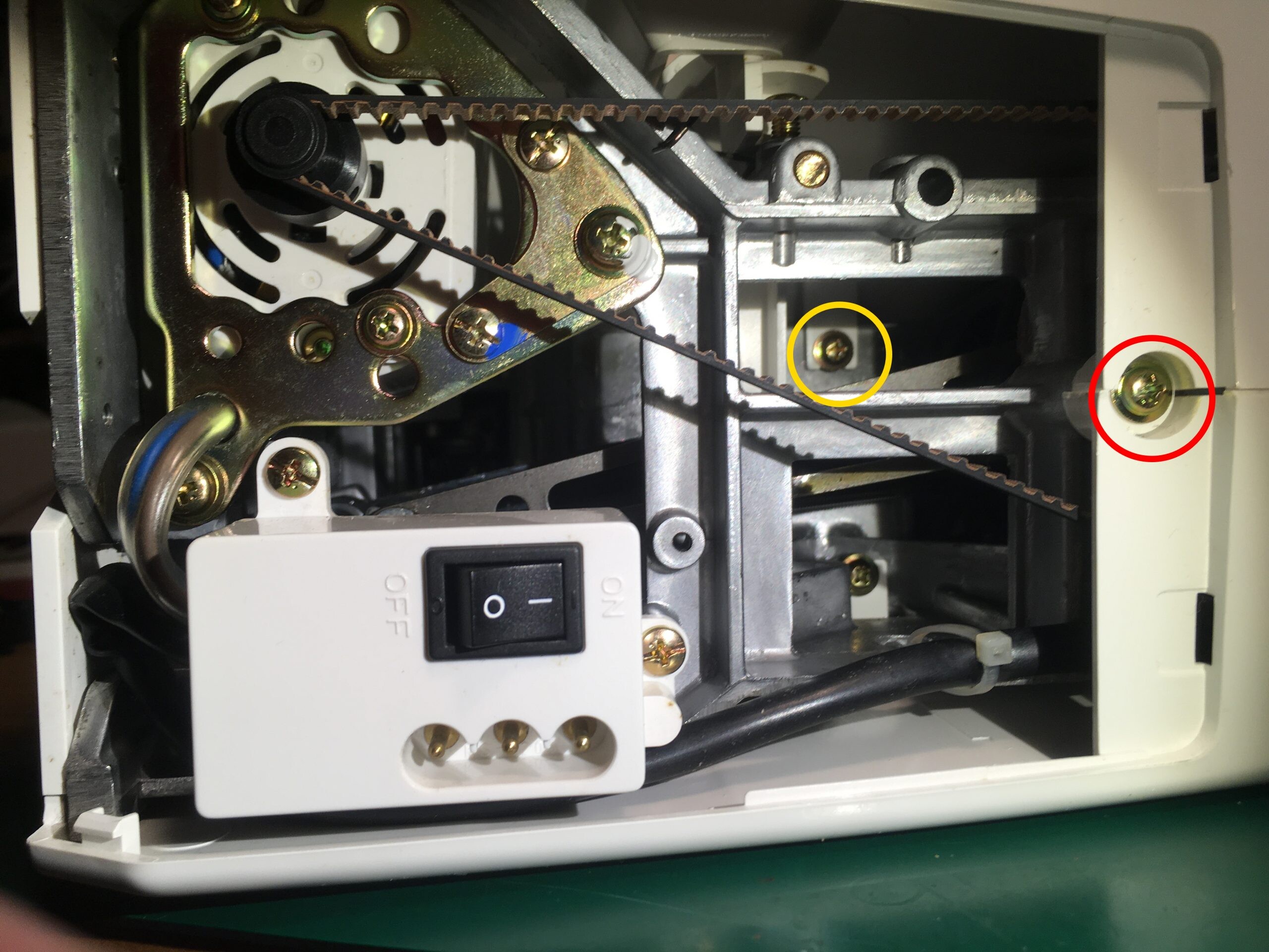
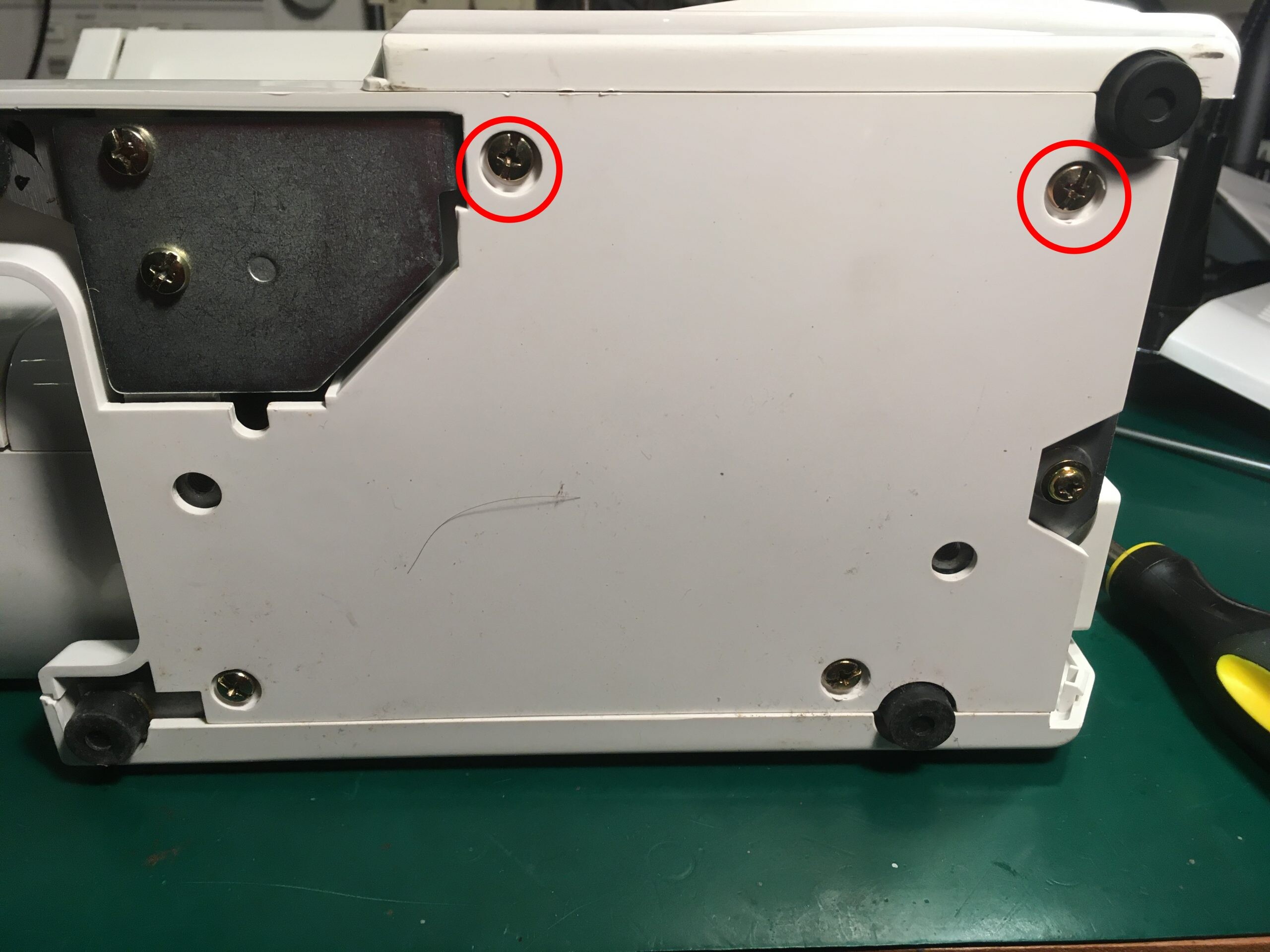
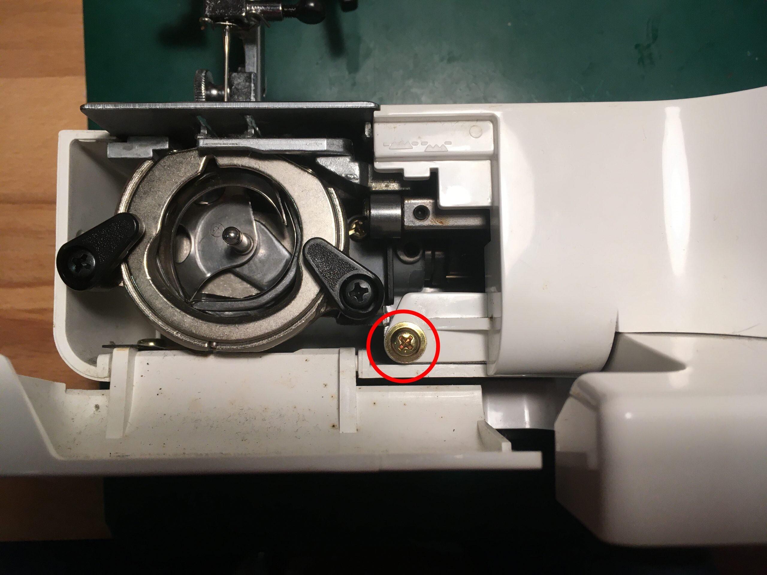
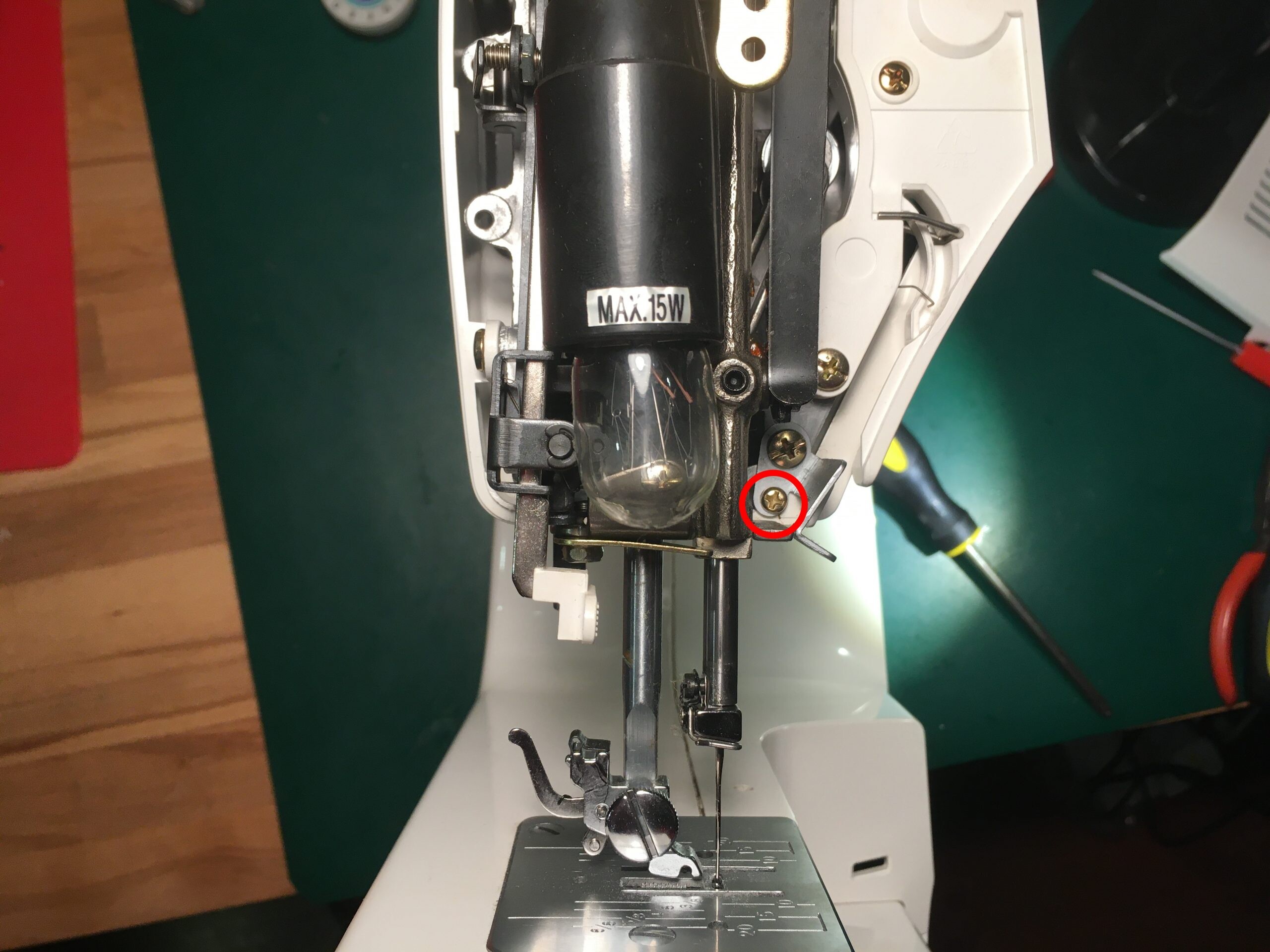
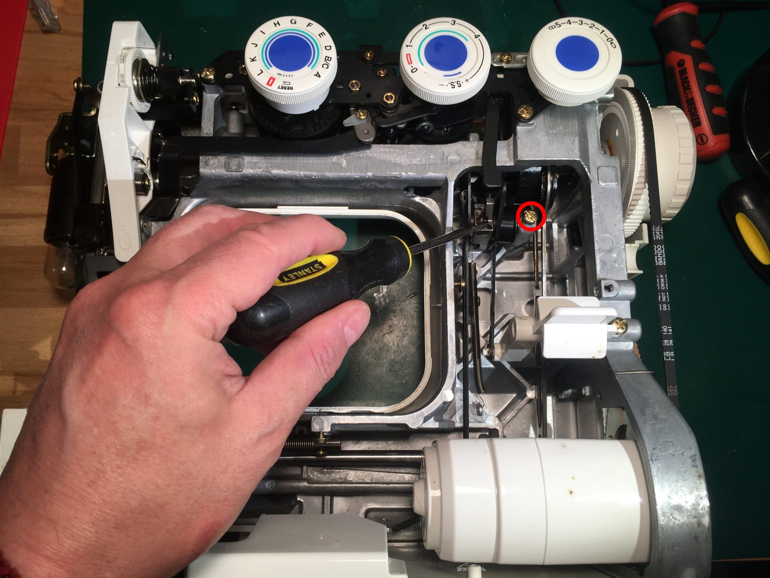
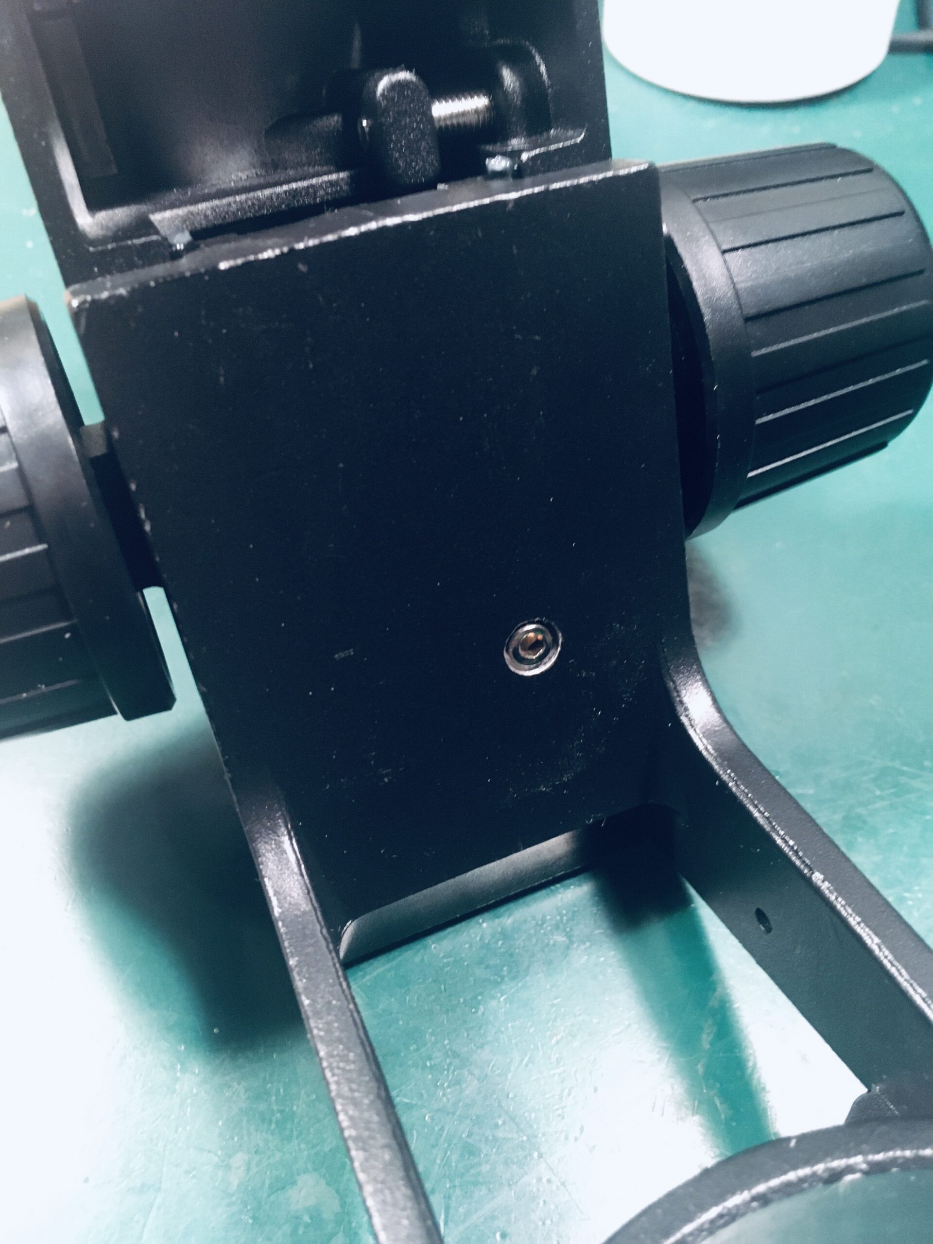
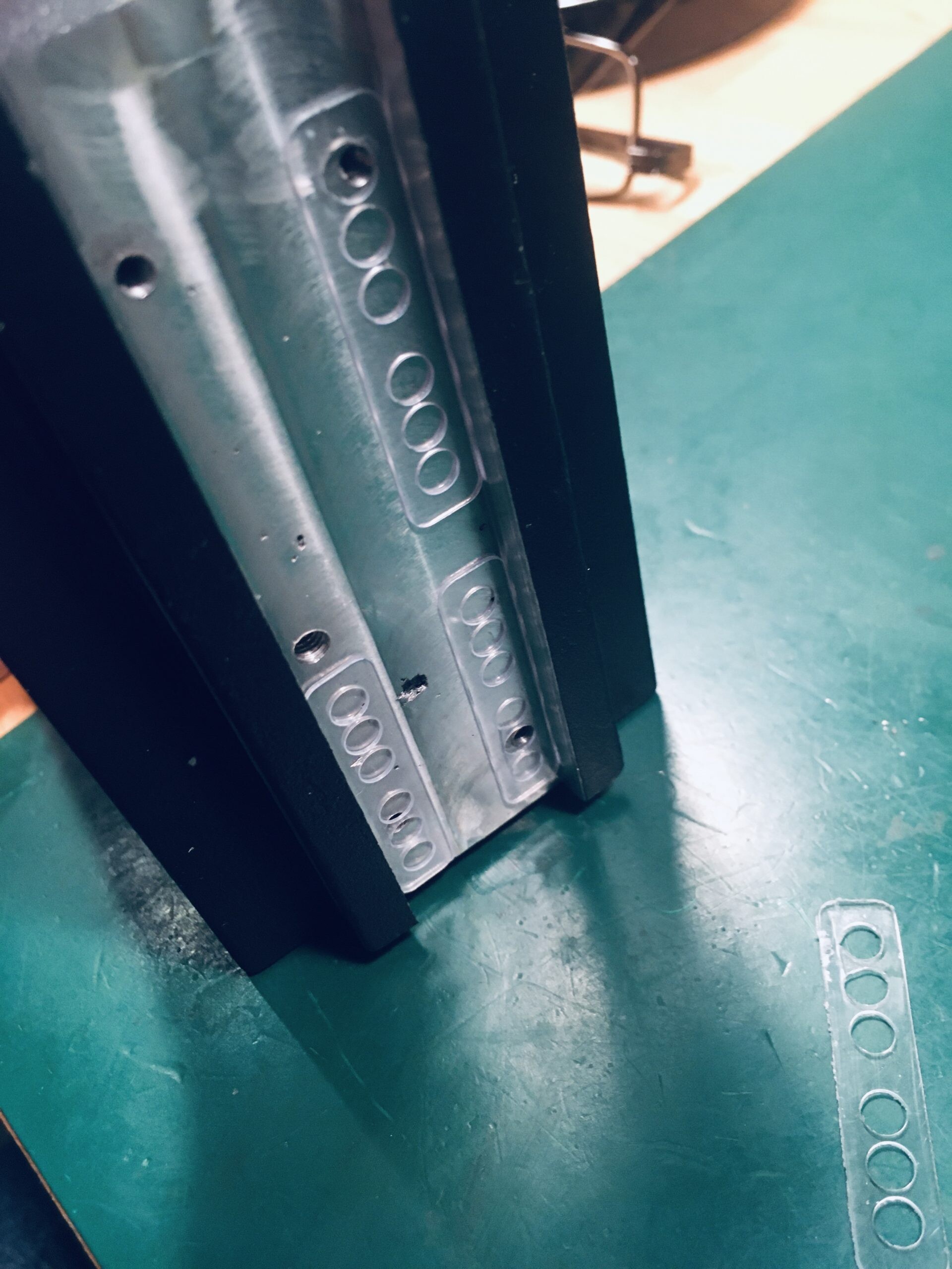
The lump of metal indicated was the problem. It was not retracting when the reversing lever was released. Some cleaning and light oiling helped but the final solution was to slightly loosen the screw marked in red.
Reassemble and all was well

This Leitch studio clock is designed to work with a timecode signal for best accuracy. Timecode generators are expensive so I built one with an ESP32 dev board.
SMPTE/EBU description here and the bit format of timecode here
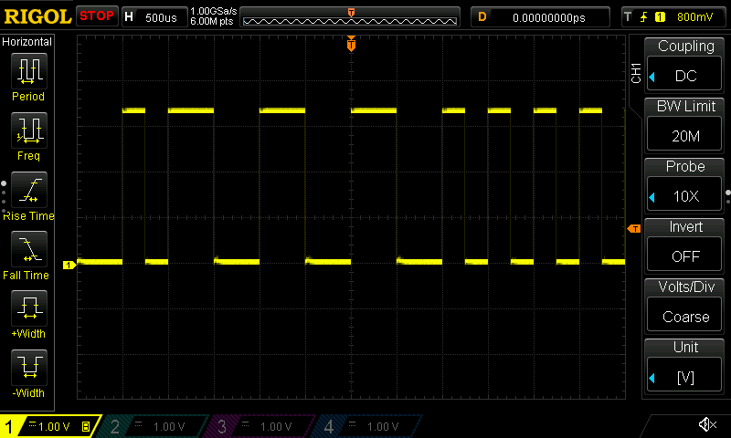
The timecode signal is a stream of digital data, 80 bits for each frame of data. In Europe there are 25 frames per sec (EBU) and in the US 30 (SMPTE). Each bit is encoded in Manchester style, with a signal inversion at the start of each bit period and a further inversion halfway though the bit if it’s a “1”.
Here is a snapshot of the generated EBU waveform representing 010000001111
For the software we just need an accurate source of time and accurate pulse generation.
Time is obtained from the internet NTP server using the ESP32 Arduino library to keep the ESP32 local time in sync with NTP and to handle GMT/DST issues.
A hardware timer is set to fire every 250uS (for EBU) to output start bit and mid bit transitions. When all 80 bits have been sent the frame counter is incremented. When all frames have been sent the whole data packet is updated with the current time and the process repeats.
Source code: https://github.com/ynformatics/SMPTE
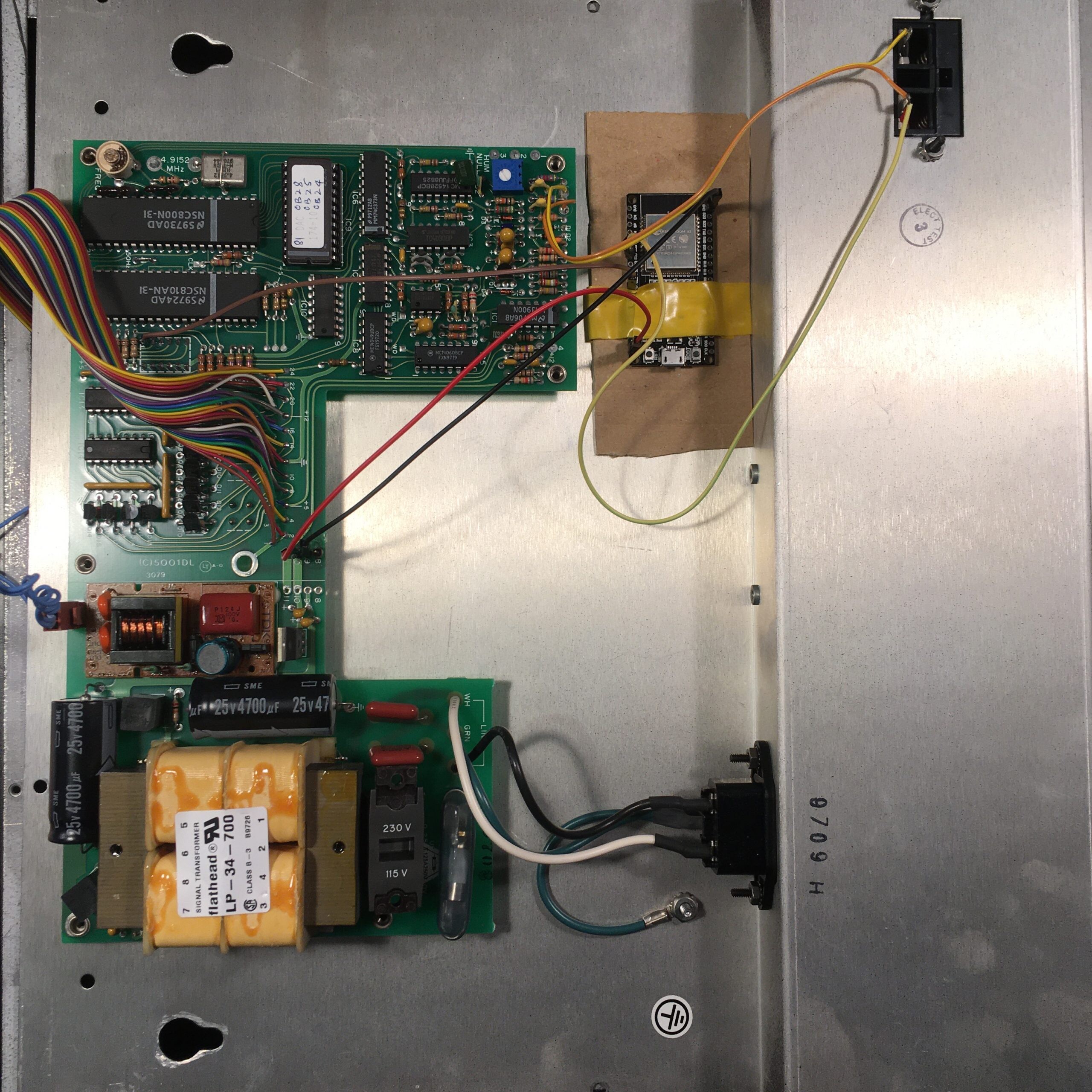
Rather than using a separate enclosure I fixed the ESP32 module inside the case. A source of 5V power is available on the main PCB and there is a spare selector switch available for entering configuration mode. The timecode signal output is wired directly to the input of the clock. If needed this can be daisy chained to other clocks.
Here is a video of the modified clock powering up. There is a short delay while connecting to WiFi and getting the time. Once the timecode data starts, the clock registers all hands to the 12 o’clock position, moves them to the correct time and then maintains time in sync with the timecode data.

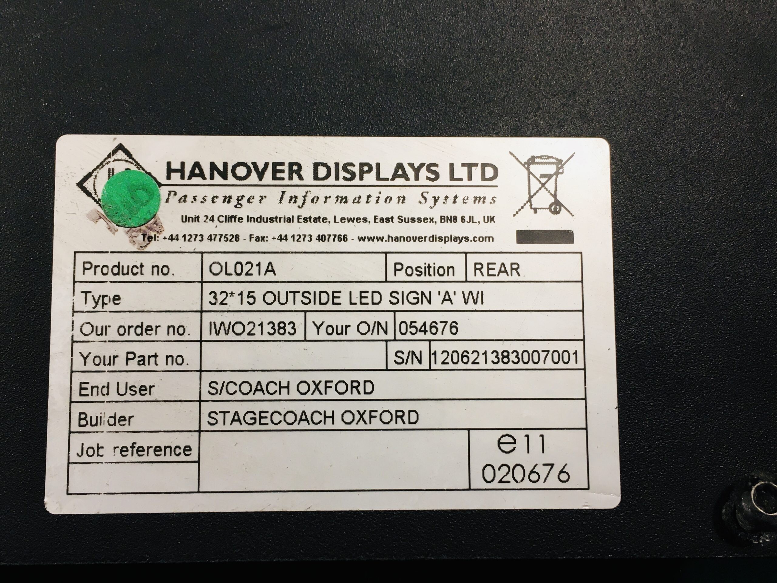
This sign is programmable via RS485 (the orange connector) but uses proprietary hardware and software so is ripe for reverse engineering. The 8 pin ribbon cable to the display board suggests a serial protocol and probing with an oscilloscope showed 0-5V digital signals. Time to attach a logic analyser.
Here is the overview on start-up:

This looks like some initialisation data and then regular data transmission every second. There is a 100Hz pulse train on pin8 (heartbeat from the display?) and a delayed pulse on pin6 about 15ms after each data transmission
Here is a zoomed-in trace for one of the data transmissions:

So definitely SPI style with a rising edge 2.4 MHz clock on pin5 and data on pin4. By default, the display powers on with the top-left led lit. The ’80’ byte in the first set of data suggests the data is being sent left-to-right, top-to-bottom, MSB first. The pixel data is gated by pin3 (active low). Each row of display data is preceded by a header, ‘3E’ for the first row and ‘BE’ for the second. Header data is gated by pin2 (Active High). Some further experiments showed that pin7 accepts an analog voltage to set the display brightness (0-5V).
In summary the function of the connector pins is:
Now we have enough info to create a prototype. I used a Wemos D1 Mini (ESP8266) which has hardware SPI and WiFi support. 5V power is available from the sign itself so no other hardware is needed. Here are the pin mappings:
| Hanover Pin | Wemos Pin |
| 1 | GND |
| 2 | D1 |
| 3 | D2 |
| 4 | D7 (MOSI) |
| 5 | D5 (SCK) |
| 6 | D3 |
| 7 | D4 |
| 8 | Unused |
Some code was written to implement the above protocol. It subscribes to the MQTT topics “hanoverled/display” (64 bytes of display data) and “hanoverled/brightness” (0-1023) and updates the display as these topics change.
Here is an extract of the code showing the main display routine. It accepts 64 bytes of data being the pixel values in left-to-right, top-to-bottom order. Not sure what the header values mean so just used the captured values 3E and BE. The ‘EOT’ pulse at the end of transmission is required otherwise the display does not update properly.
void UpdateDisplay(byte data[64])
{
   SPI.beginTransaction(SPISettings(2500000, MSBFIRST, SPI_MODE2));

   // meta data row 1
   digitalWrite(MS, HIGH);
   SPI.transfer(0x3E);
   digitalWrite(MS, LOW);

   // pixel data row 1
   for(int i = 0; i < 32; i++)
   {
      digitalWrite(DS, LOW);
      SPI.transfer(data[i]);
      digitalWrite(DS, HIGH);
   }

   // meta data row 2
   digitalWrite(MS, HIGH);
   SPI.transfer(0xBE);
   digitalWrite(MS, LOW);

   // pixel data row 2
   for(int i = 32; i < 64; i++)
   {
      digitalWrite(DS, LOW);
      SPI.transfer(data[i]);
      digitalWrite(DS, HIGH);
   }
   SPI.endTransaction();

   // pulse EOT line
   delay(15);
   digitalWrite(EOT, HIGH);
   digitalWrite(EOT, LOW);
}
To test the display a version of Conway’s game of life was written. Random start populations are generated, evolved and sent to the MQTT “hanoverled/display” topic. The program generates a new population if a game starts to repeat.
Here is a video of the sign in operation:

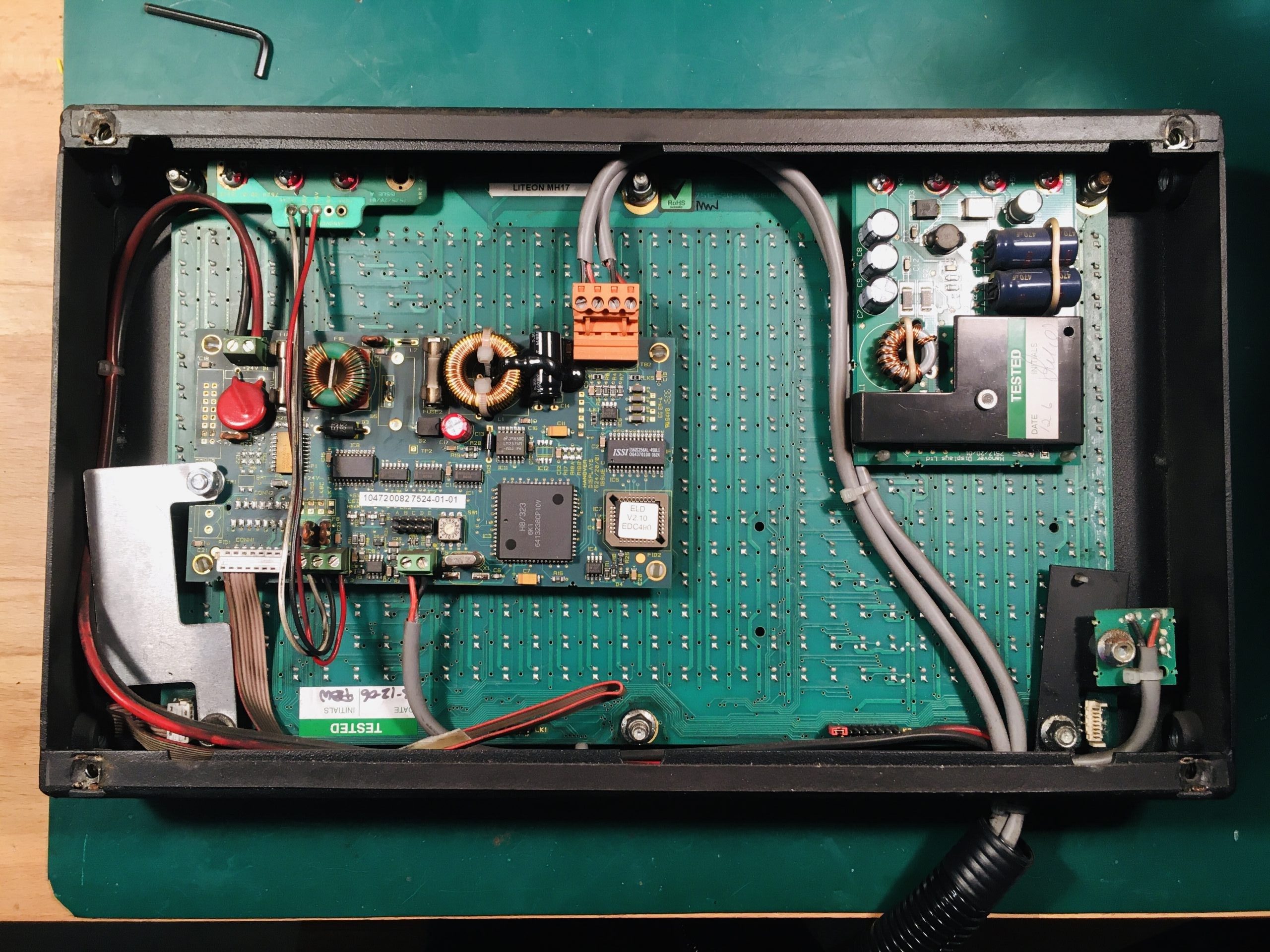
I bought this Sinclair calculator off eBay with the intention of repairing it. The power supply rails, LED display and driver chips were working fine. The keyboard had several keys that did not show any connectivity which could be fixed. But the main C-595 calculator chip was faulty and outputting random signals.
The C-595 is of course unobtainable these days, so could we replace it with a suitably programmed Arduino chip and bring it back to life?
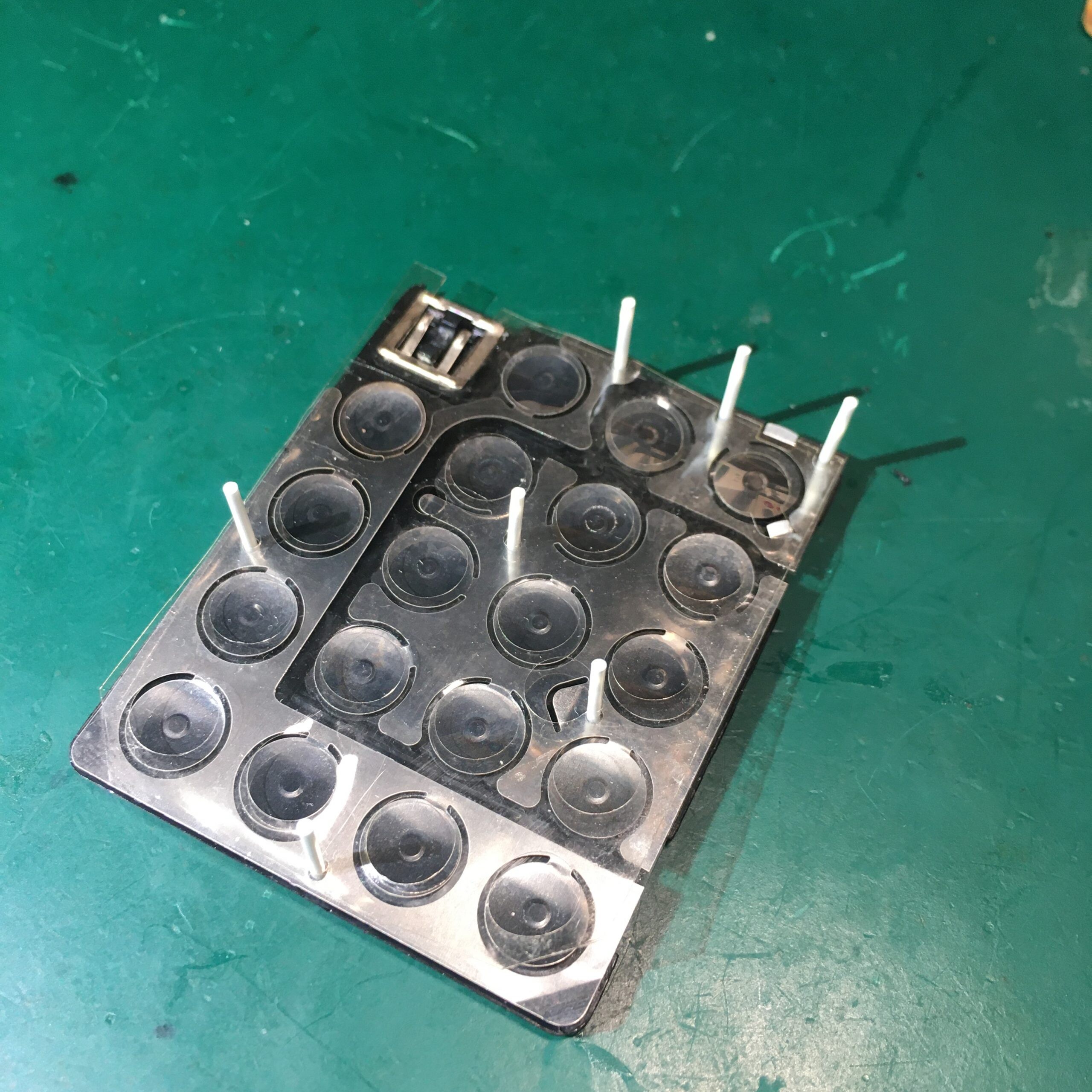
First job was to fix the keyboard. Several keys were not functioning so this needed a tear down and clean.
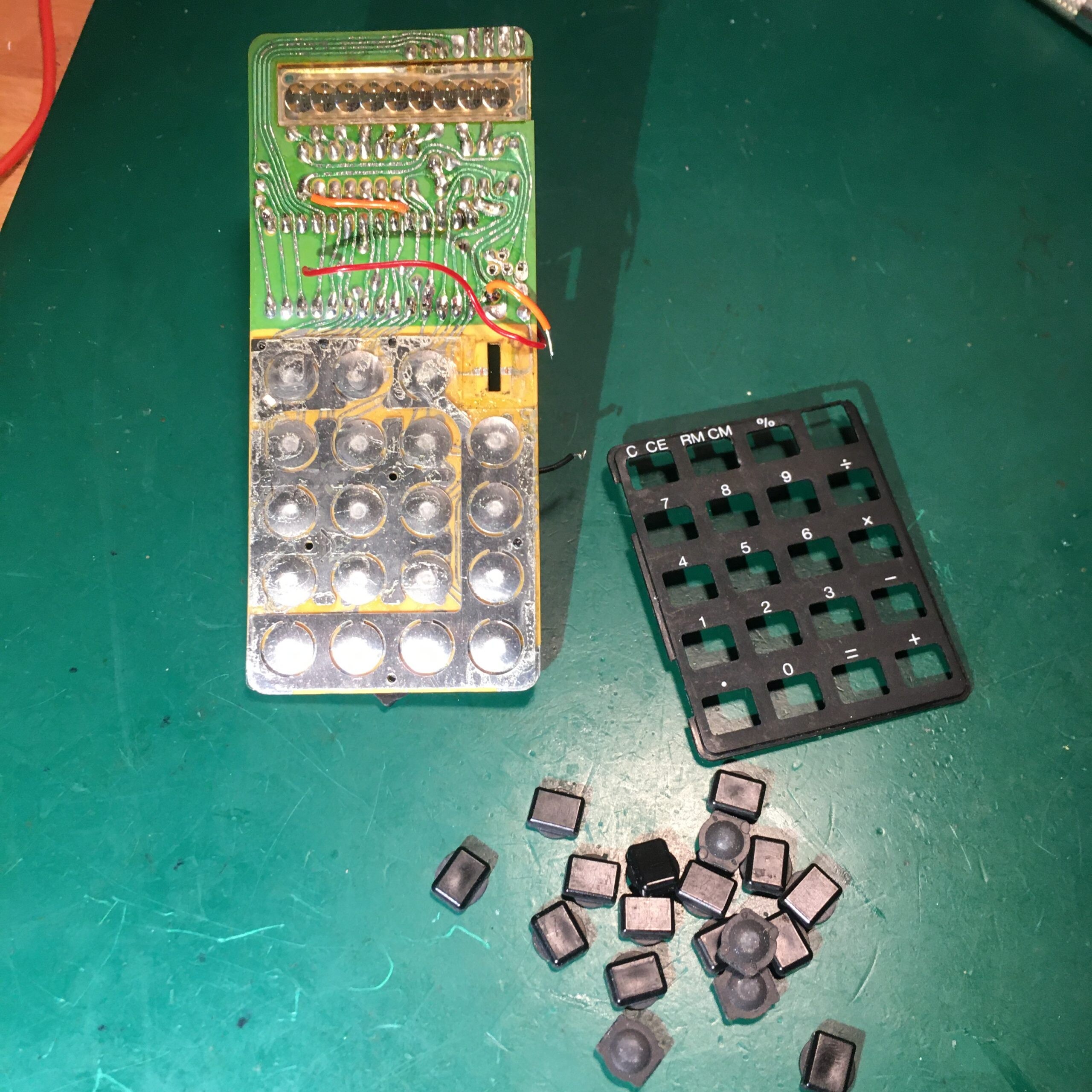
The keyboard was held in place by plastic pegs which naturally snap off when disassembling! Some small holes were drilled in the plastic frame using a hand held 1mm CNC drill bit taking care not to go through to the other side. Small lengths of 1mm ABS rod were then glued into the holes and melted with a soldering iron to keep the keyboard layers tightly sandwiched together.

With the keyboard working we turn attention to the main calculator chip. The plan was to design a small PCB carrier for an ATMega328 chip that could plug in in place of the original chip.
A datasheet is available for the C-595 (local copy here) and after some reverse engineering we arrived at the following schematic:
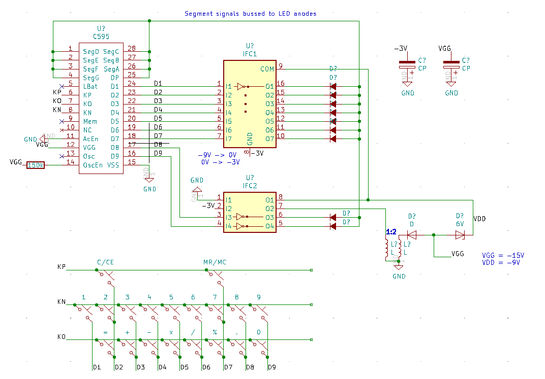
The C595 runs with a positive earth, so we’d have to install the Arduino upside down. A bit of a brain ache but it should work. I wanted to use the existing driver ICs to minimise changes.
Removed the C595 IC and replaced with a socket. Removed the coil to disable 15V and 9V generation. Added a jumper wire to supply -3V battery power to an unused pin 10 on the socket.
The LED display is a 9 digit, seven segment common cathode device. To turn on a segment requires the segment line to be at 0V and the corresponding digit cathode at -3V. Allowing for the voltage inversion by the driver and the upside down Arduino, that corresponds to a HIGH for the segment and a HIGH for the digit.
To add to the fun the keyboard is multiplexed to the digit driver pins. An INPUT_PULLUP pin on the Arduino will pull to 0V, so we need to strobe the digit pins with -3V (LOW) to detect a change in state on the KP, KN and KO input pins.
We need 17 digital outputs and 3 digital inputs. To run at low voltage we use the internal oscillator which helpfully frees up pins PB6 and PB7 for use as GPIO.
The software was developed initially as a prototype running on an Arduino Nano. It runs in a loop with three main functions; update the display, read the keyboard and update the calculation when a key is pressed. Updating the display is slightly complicated by the fact that the circuit uses the same pins to enable display digits as well as drive the keyboard. We need to take care to blank the display while the keyboard is polled. For the calculator part of the software a simple state machine is used in conjunction with a custom decimal floating-point library. Firmware can be found in this github repo
Here is a picture of the prototype:

The case wouldn’t close properly using the prototype so a small PCB was designed around a bare bones ATMega238P to fit in the C595 socket. The ICSP and Tx/Rx pins were connected to exposed pads for testing purposes.


An Arduino Uno was used as a programmer to flash the firmware to the ATMega using these pin connections.
PCB    ->  Arduino Uno
PIN 15 (VCC) -> 5V
PIN 10 (GND) -> GND
PIN 7 (KO, MOSI) -> 11 (MOSI)
PIN 8 (KN, MISO) -> 12 (MISO)
J103 pin 5 (~RST) -> 10
PIN 16 (D9, SCK) -> 13 (SCK)
To support the bare board, definitions were loaded from: https://mcudude.github.io/MiniCore/package_MCUdude_MiniCore_index.json
We use the factory defaults of 1MHz internal oscillator and BOD disabled so no need to change the fuses. Just set the drop down menu items correspondingly.
Here is a short video with a demo of the finished calculator and a quick look inside.
A simple GPIB to USB adapter using an Arduino Uno. Constructed following: http://egirland.blogspot.com/2014/03/arduino-uno-as-usb-to-gpib-controller.html
A 24-way connector (RS 239-1207) was used for the GBIP connector and wired to the Arduino with two lengths of cat 5 cable as follows:
cable 1 pin mapping
GBIP	Wire	Uno
1	wh/or	A0
2	or/wh	A1
3	wh/bl	A2
4	bl/wh	A3
13	wh/gr	A4
14	gr/wh	A5
GND	wh/br	GND
GND	br/wh	GND

cable 2 pin mapping
GBIP	Wire	Uno
5	wh/gr	12
6	gr/wh	11
7	wh/br	10
8	br/wh	9
9	bl/wh	8
11	wh/bl	7
15	or/wh	4
16	wh/or	5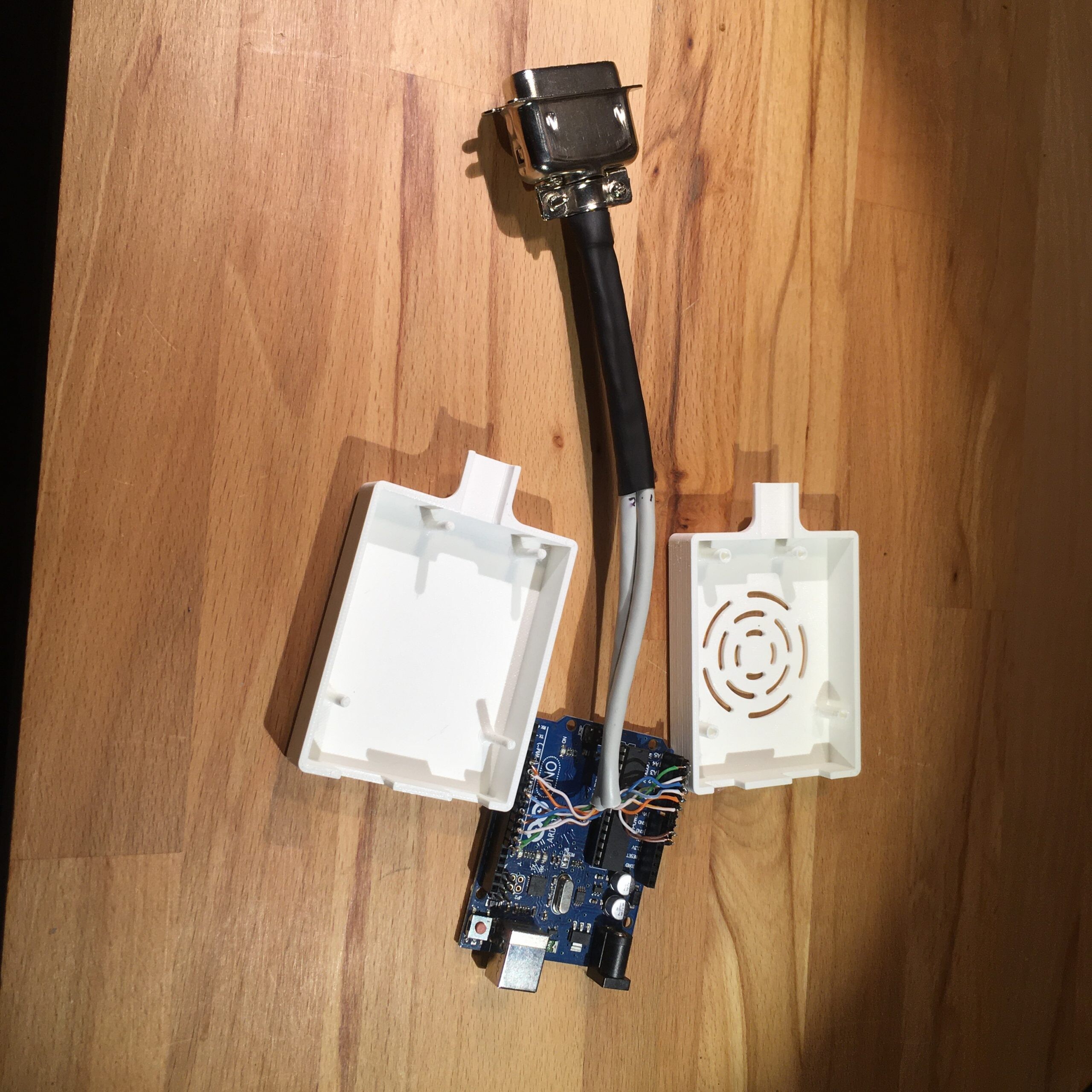
A 3D printed case was designed in Fusion 360. CAD files available here.
The Uno was programmed with GPIB6.1.ino available from Emanuele’s website.
I have a few roller blinds ripe for automation. The first attempt used a stepper motor with a 3D printed cog to pull the cord.

This worked but had the look of a Heath Robinson / Rube Goldberg love child so I looked for a neater solution.
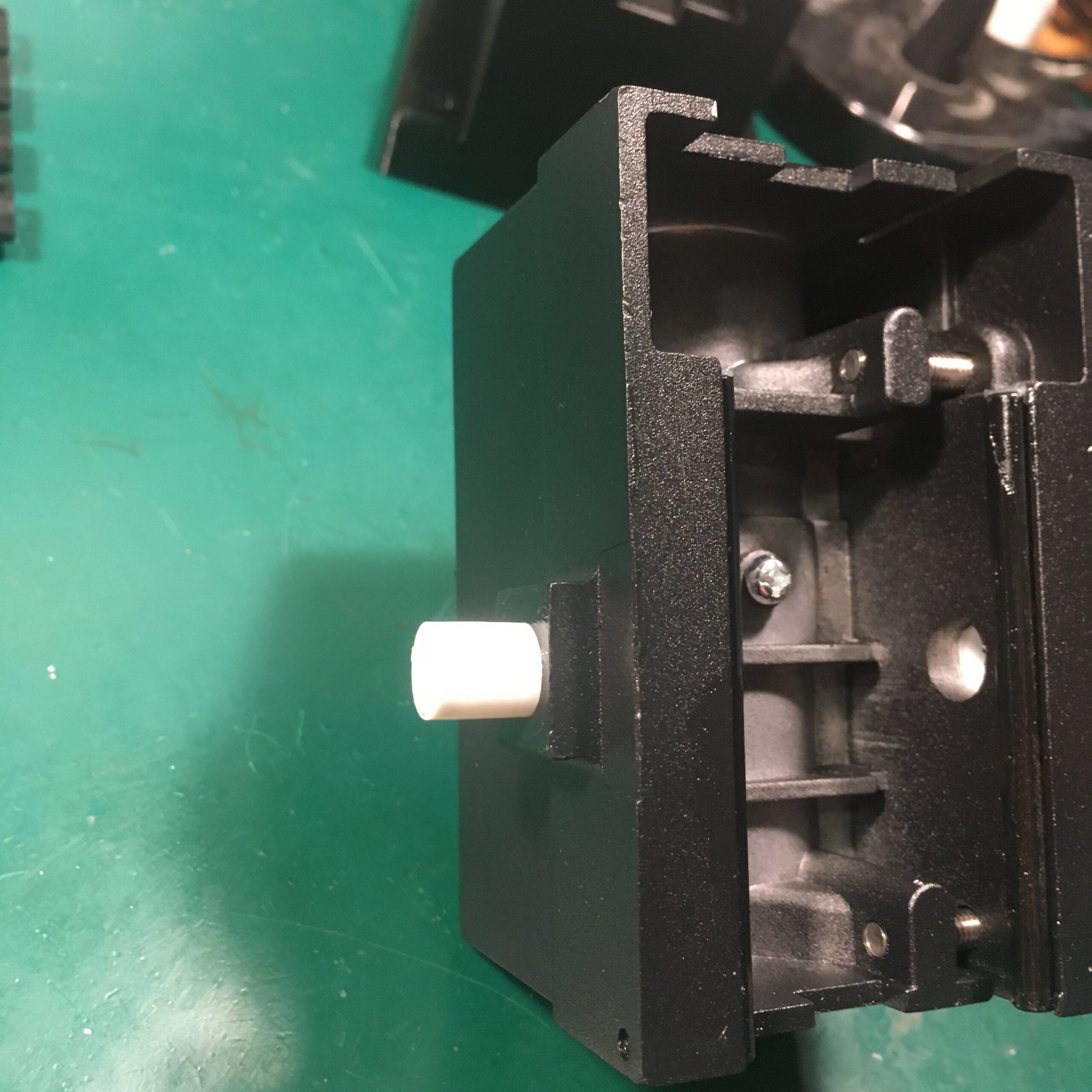
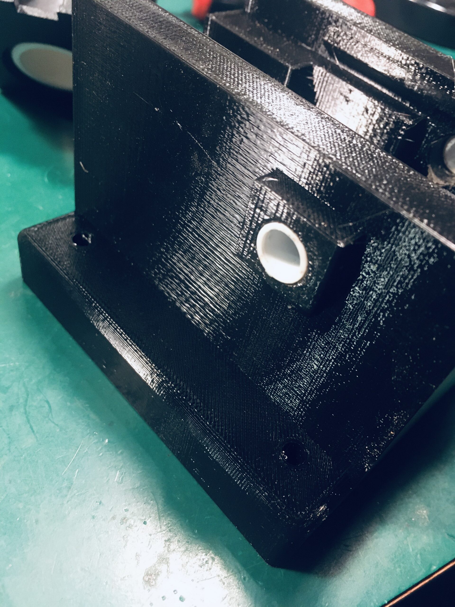
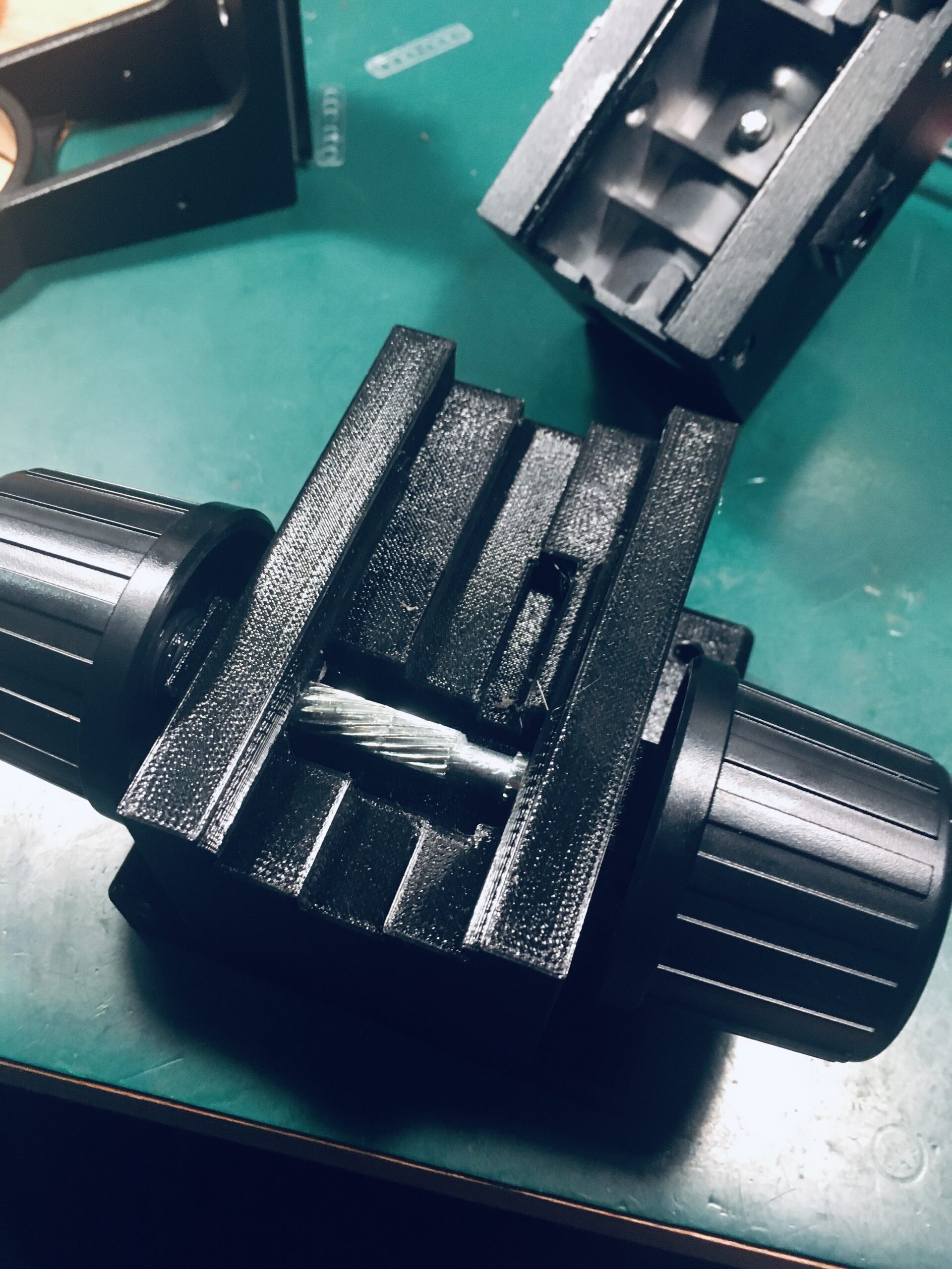
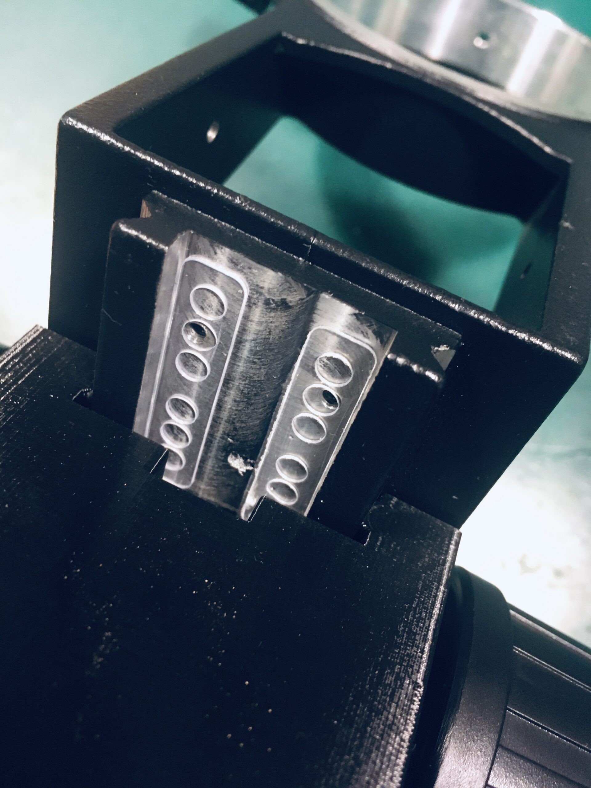
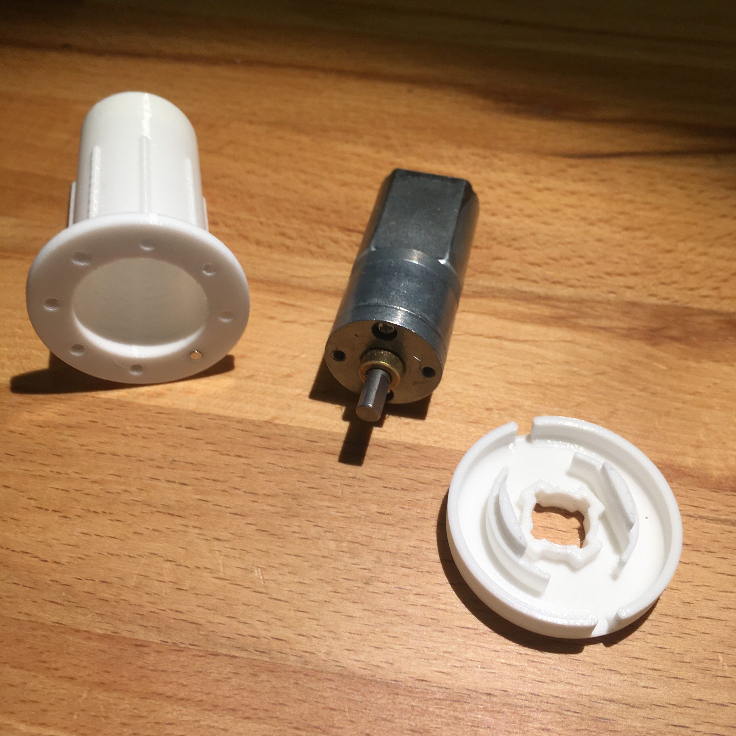
Tubular motors that fit inside the roller tube can be bought online but were rather expensive and bulky for my purposes so I opted for a more compact design. Taking measurements from the existing blind pulley mechanism and a suitable 30 RPM 12v DC motor with 20mm external diameter:
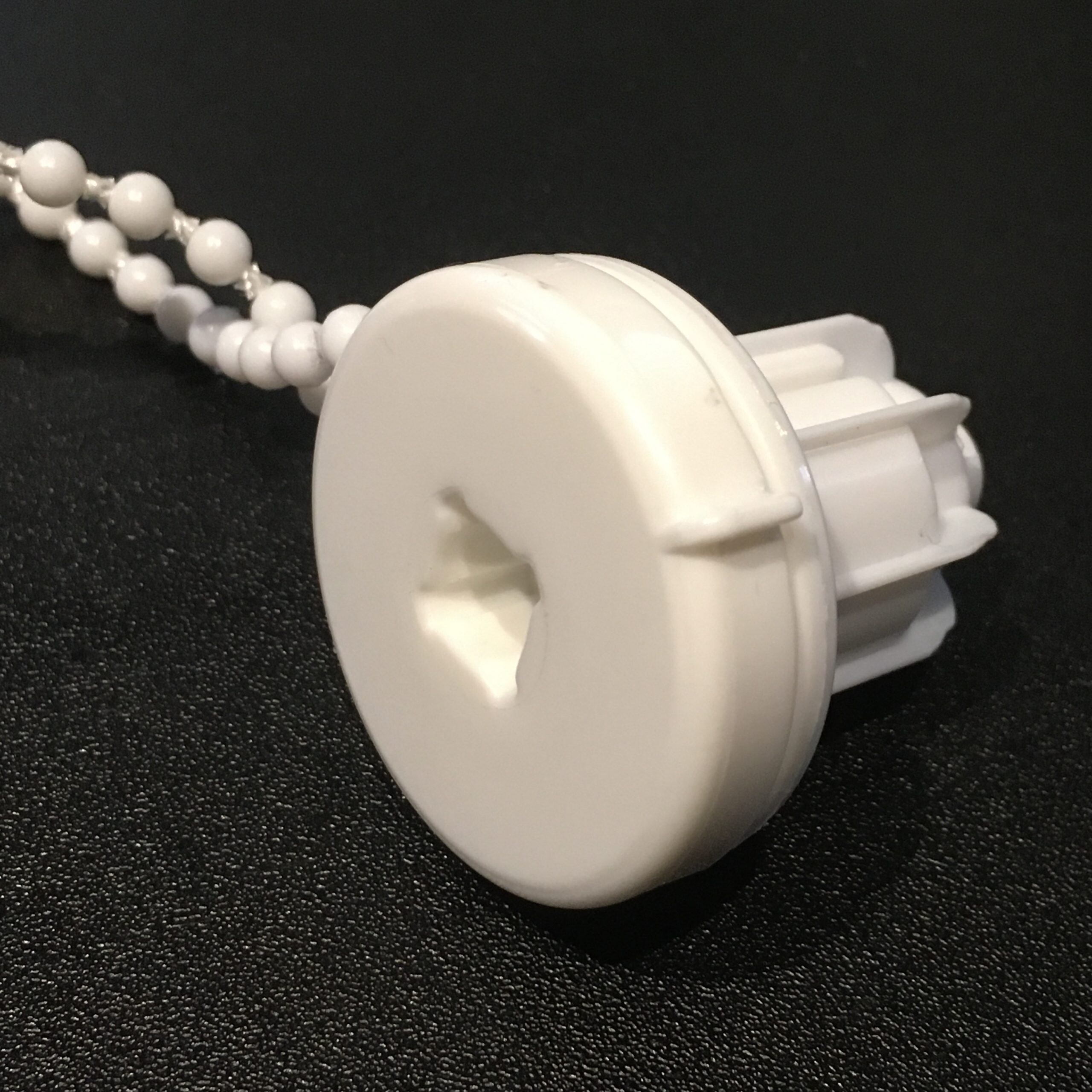

let me design a replacement in Fusion 360
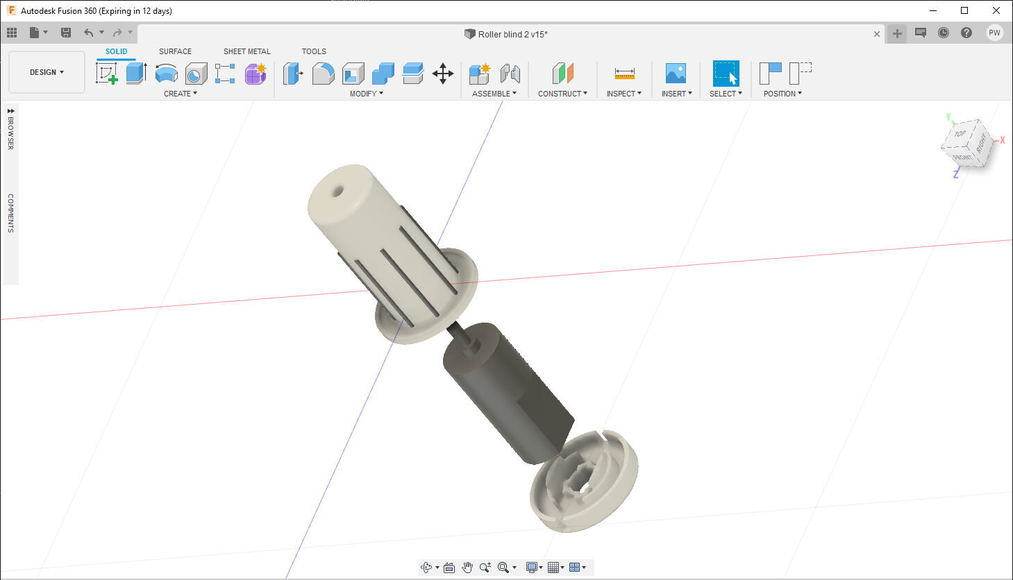
Using a DC motor requires some sort of encoder to keep track of the blind position. I opted for a magnet/hall sensor mounted in the drive mechanism. This keeps the the sensor unobtrusive but limits the resolution to one revolution (about 10 cm of blind travel in my case). I hoped that combining this with timing data would be accurate enough. It was.
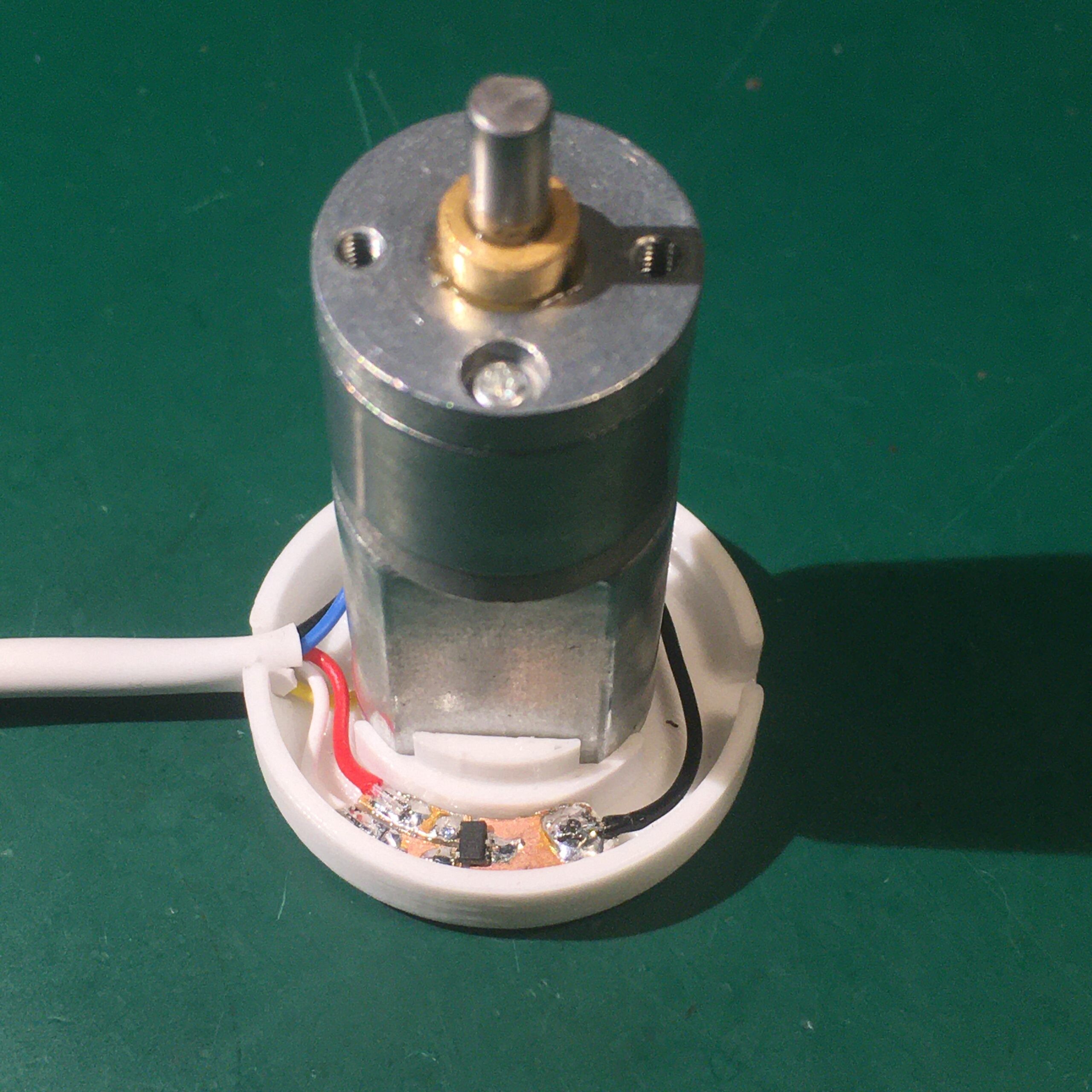
Output from the printer. Note a small 2 x 1 mm magnet has been inserted in one of the holes.
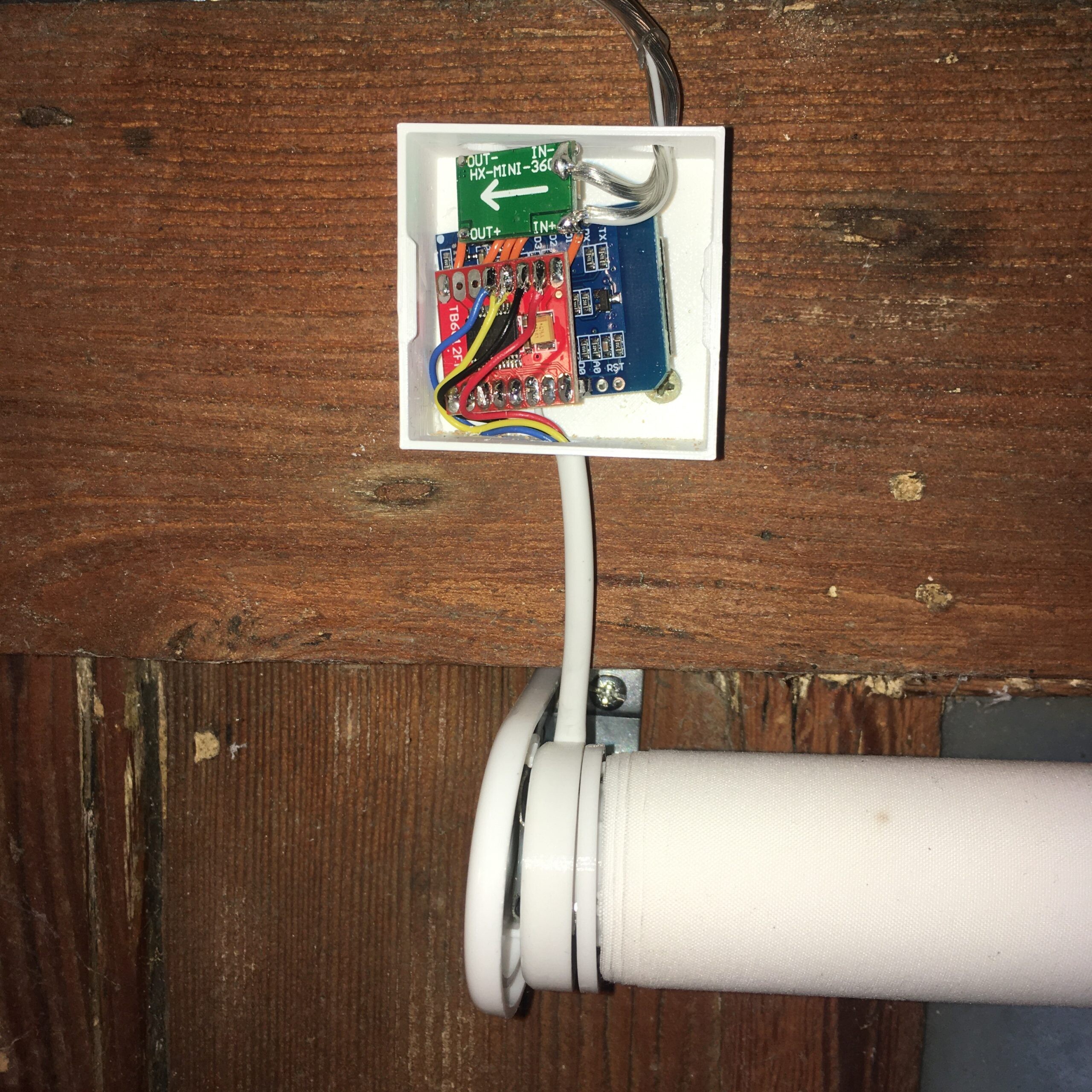
I hand carved a small PCB to hold the Si7025 hall effect sensor and connected everything up.
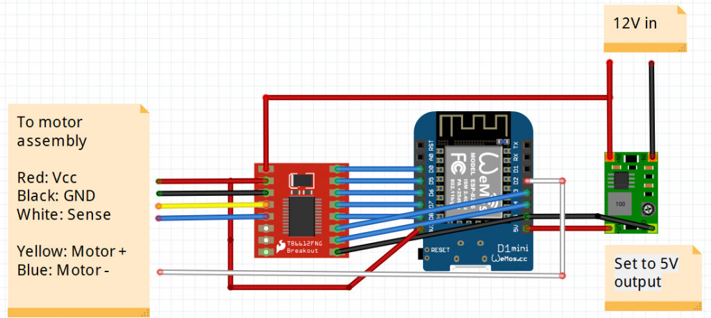
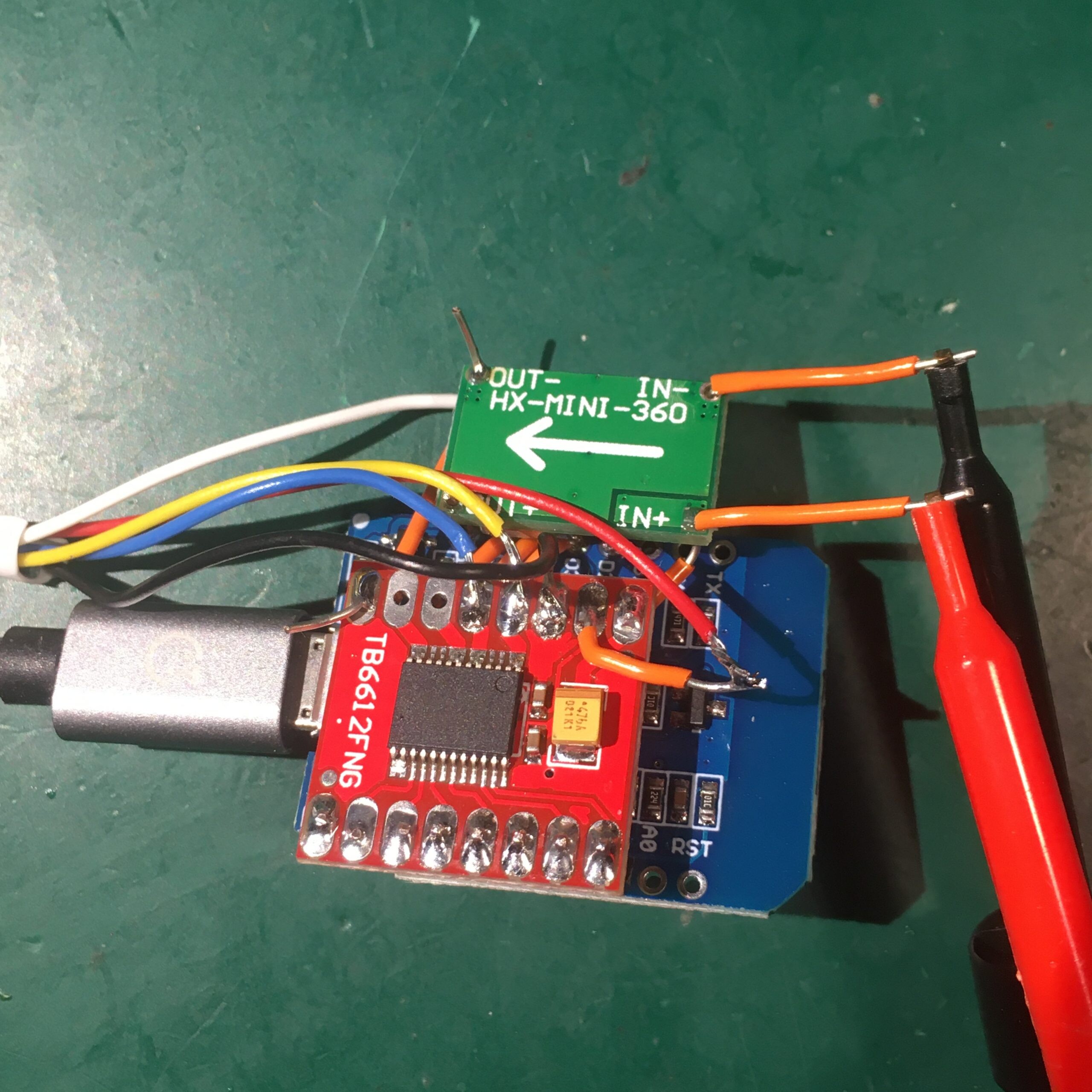
For the controller I used a Wemos D1 mini with a TB6612FNG driver module which can handle up to two DC motors. A small buck converter supplies 5V for the electronics from the 12V motor supply. All wired together in point to point style:
The code was written using the Arduino IDE. One unexpected problem was occasional glitches on the sensor output. This screenshot of the sensor output while running at 30 rpm shows the expected high -> low transitions as the magnet passes the sensor, but with the occasional spurious pulse. These pulses were always less than 1ms duration so are simply filtered out in software.
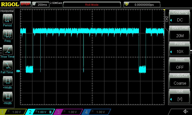
To move the blind to a given position, the software moves to the next magnet home position, then counts complete revolutions while timing how long each revolution takes, and then keeps the motor running for the required time to move the remaining distance.
An MQTT API was implemented, controlled from a Node Red flow.
A small case to contain the electronics was 3D printed and wired up to a 12 V power supply.
And here are the blinds in action:
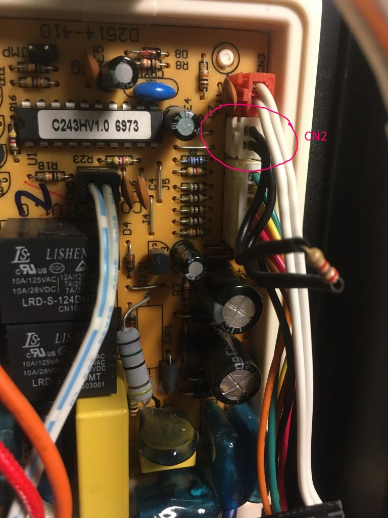
I have a three year old DeLonghi DEM10 dehumidifier whose low temperature warning light is now permanently on. The unit is indoors where the temperature never drops to such low levels.
Internet searching suggested a faulty capacitor on the main PCB. I replaced this but to no avail.
The schematic shows that connector CN2 leads to the temperature sensor. Disconnecting this and measuring with a multi-meter showed a sensor resistance of 650 ohm. I experimented with a few different resistances and it seems that anything above about 1500 ohms turns the warning light off. I settled for 2k7 ohms, cut the sensor lead, soldered it in place and covered with heat shrink.
All working now!
This project couples a variac with an isolation transformer.
Two design decisions to make:
1. Does the isolation transformer go before or after the variac? Here it was placed after the variac as the variac was rated to 4A and the transformer 5A. Any turn-on surge current will be less through the variac.
2. Is an earth connection passed through to the output socket? No, because it’s an isolation transformer 😉 For convenience the earth connection is made available separately on the front panel.
The schematic is straightforward:
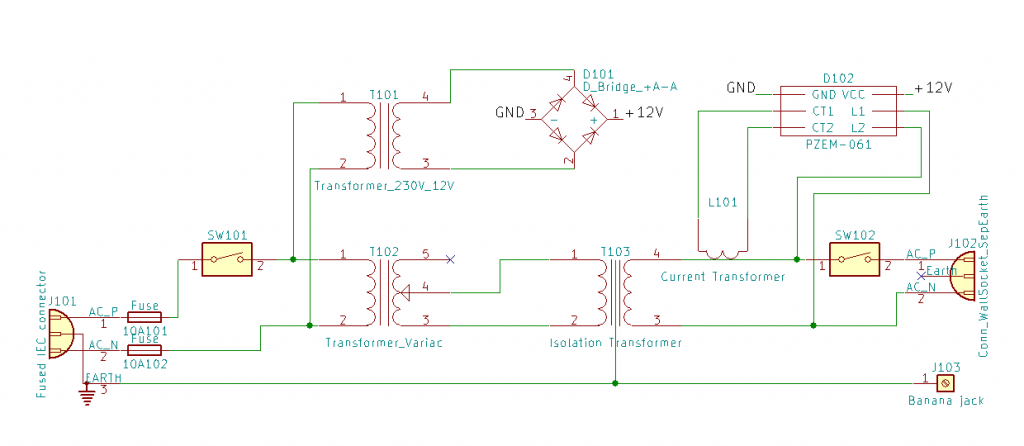
A PZEM-061 module is used to display output voltage, current and power. It is hacked (ref 1) to run off a separate 12V supply which is sourced from a small transformer to maintain isolation.
A box was constructed from MDF and plywood to contain the hardware.
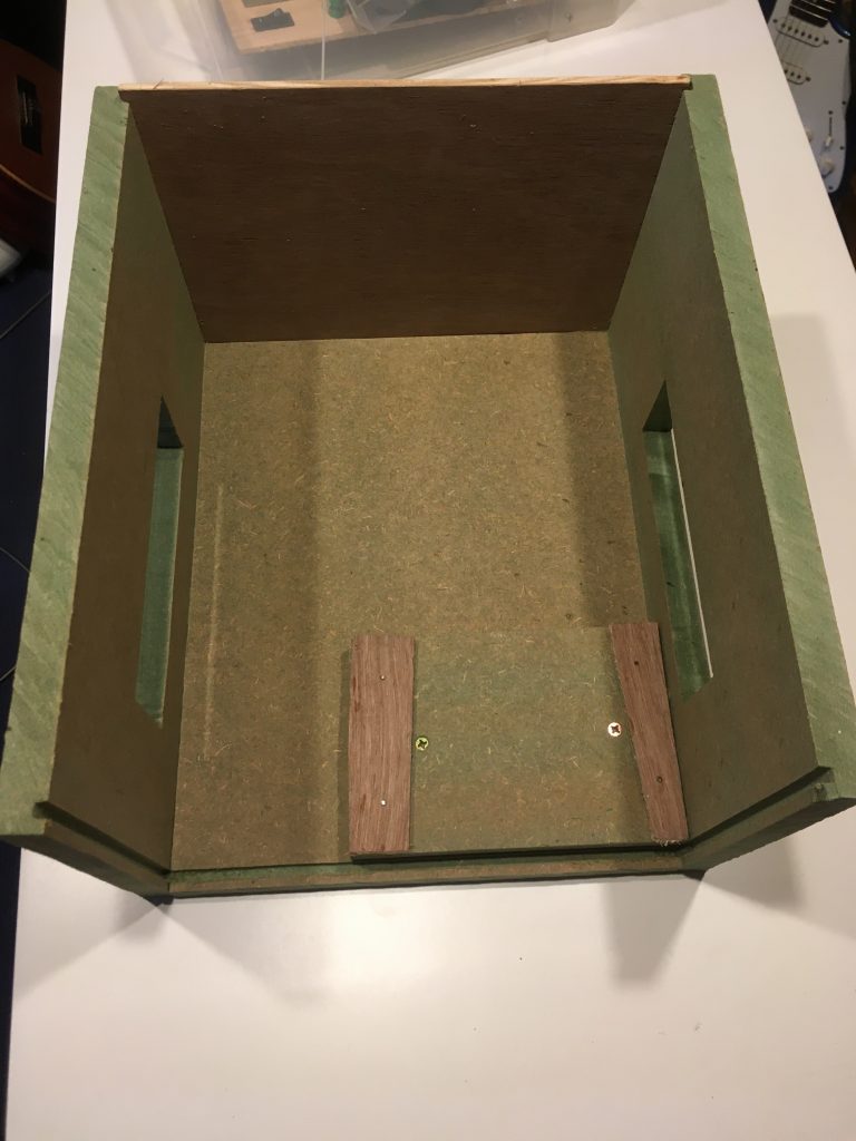
With two large transformers the unit weighs in at 25 kg.
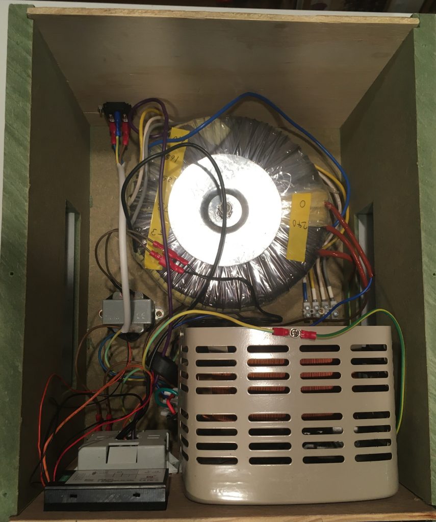
The variac was positioned so it pokes through a hole in the front panel. Re-using its original scale gives a rough idea of the voltage and tidies up the hole. Even the rubber feet were reused.
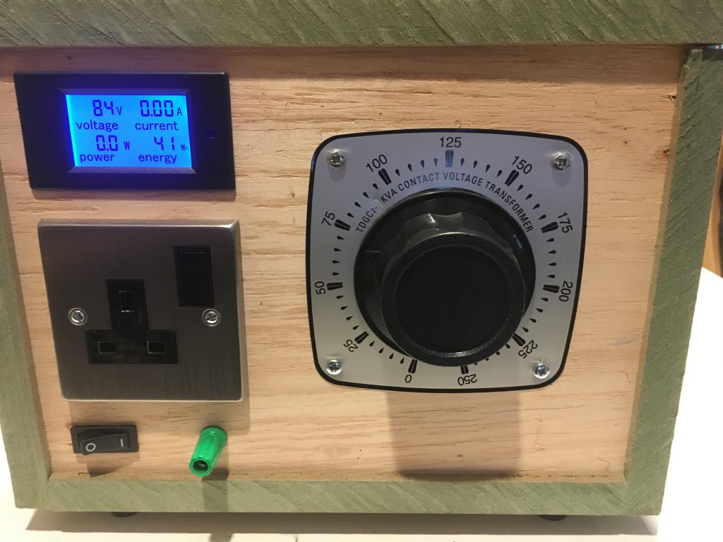
All finished and ready to use.
Refs: